P12
CR1
1N495B
1
GROUND
A
H2 T1 X1
L1
X2
R3
R5
R4
R2
R1
X3
C3
3
H1
VOLTAGE
C
C4
ADJ RHEO.
CR2
Q2
C6
4
R20
1N485B
TO EXCITER
D
2N2904
R6
TERMINAL K
Q1
03
R13
R19
5
R18
R17
TO EXCITER
2N1613
2N1613
E
TERMINAL M
R9
R14
R7
2N1490
CR3
Q6
C5
R22
R21
1N485B
VR2
04
1N753A
R12
2N1613
2N1485
Q5
C2
C1
VR3
R23
1N753A
R8
R11
R10
2
TO EXCITER
B
TERMINAL L
HEAT SINK ASSY
R16
6
R15
PRINTED CIRCUIT BOARD ASSY
ASf07035
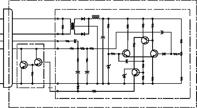
Figure 7-35.--An ac voltage regulator (VR2) simplified schematic.
circuits R6, R7, and R8. The voltage tapped at R7, a
The circuit consists of resistors R17 through R22 and
capacitors C1, C2, and C6. Combined, they develop a
variable resistor, is applied to the base of Q1 through
single voltage to the base of transistor Q1. This causes
R9 and CR3. Transistors Q1 and Q3 are arranged in a
the differential amplifier to react faster to transient
differential amplifier circuit. This arrangement
voltage changes. Diode CR3, in series with the base of
amplifies the difference between the reference voltage
Q1, improves the temperature stability of the circuit.
and the voltage signal of the generator output. The
Capacitor C5 reduces ripple voltages and prevents
output of Q1 is an error signal. It biases the base of Q2
for further amplification. The collector output of
the varying collector current of Q4 from causing a
transistor Q2 drives the base of the emitter follower
varying load on the voltage sensing circuitry.
stage Q4. The emitter follower stage Q4 drives the
Darlington amplifier Q5 and Q6.
AC Circuit Protection
The Darlington stage Q5 and Q6 controls the
amount of dc current that flows to the exciter fields. If
High capacity power generating equipment must
the generator's output voltage rises above the desired
have a system for sensing fault conditions in voltage
value, the differential amplifier amplifies the increased
and frequency. The sensors used to detect fault
difference between the dc circuit voltage and the
conditions are located in a PROTECTIVE PACKAGE.
reference voltage. The series of amplifiers are then
The sensors in the circuits sense overvoltage,
driven by transistor Q1. All amplifiers respond with a
undervoltage, overfrequency, underfrequency, and
high output current. This causes the Darlington
phase sequence. When one or more of these conditions
amplifier to produce a higher current output to the
occur, control relays are energized to cut off the output
exciter. This increases the field strength of the exciter,
voltage supply. The operating limits for ac voltage are
resulting in a lower generator field excitation. This
105 to 125 volts. The phase sequence must be in proper
causes a reduced generator output. When the generator
order, A-B-C.
output falls below the desired level, the preceding
Mobile electric power plants (MEPPs) that are
sequence reverses, producing more field excitation.
driven by electric motors usually do not have dc
A change in load conditions can result in transient
generators. As in the case of the MMG-1A, the
voltage changes that could cause the generator voltage
three-phase ac input voltage is stepped down by a
to oscillate around its nominal value. To prevent such
transformer and rectified to dc. Figure 7-36 shows a
simplified schematic of a similar circuit.
instability, a rate-controlled feedback circuit is used.
7-27

