module. This three-phase alternating voltage is
Q1. With Q1 conducting, the proper base voltage for
rectified by a full-wave, three-phase bridge network
Q2 is provided. Transistor Q2 is forward biased, which
consisting of diodes CR1 through CR6.
shorts the voltage for K1. Relay K1 de-energizes and
contacts 2 and 3 close. The closed contacts signal an
The magnitude of this rectified voltage is directly
overvoltage fault to the fault locator board. The fault
proportional to the ac input voltage. Simply stated, if
locator energizes the generator fault relay K9, which
the ac input voltage at terminals A, B, or C is increased,
causes the generator to turn off and the engine to idle.
the rectified voltage increases. The rectified voltage is
impressed across the self-bias circuit of transistor Q1.
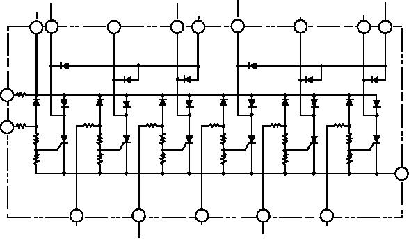
The following paragraphs describe the operation
The base voltage of Q1 is provided by the voltage
of the fault locator when the overvoltage signal is
divider circuit consisting of R1, R2, R3, R4, and R10.
received. (Refer to figure 7-51, the simplified
R3 is a potentiometer. The setting of R3 determines the
schematic of the fault locator board, and figure 7-52,
voltage divider ratio and the voltage at which Q1
the fault indicator switch circuit.)
saturates. Capacitor C1 reduces the ripple component
When the fault indicator switch is in the RUN
of the rectified voltage and maintains a more stable
position and the reset switch closed, +24 Vdc is
base voltage.
impressed on terminals 5 and 7 (fig. 7-51). The
Resistor R5 drops a proportionate amount of the
silicon-controlled rectifiers (SCR) Q1 through Q6 are
rectified voltage, and Zener diode CR8 regulates the
in an OFF condition. To be turned on, an SCR must
resultant voltage rise to a fixed value. This determines
have a positive potential available at the anode, a
the collector supply voltage of Q1 and the emitter
negative potential at the cathode, and a positive
supply voltage of Q2. The base voltage for Q2 is
potential at the gate. The gate voltage must be positive
provided through resistor R8 when Q1 is conducting.
in relation to the cathode voltage. Once the SCR is
Transistor Q2 is connected in parallel with the
turned on, it continues to conduct until the anode
operating coil of relay K1. When Q2 is not operating,
potential is broken.
K1 energizes.
When an overvoltage occurs at K10 (fig. 7-52),
During normal operation the ac input voltage is not
contacts 2 and 3 close. This presents the full
sufficient to forward bias Q1. This causes Q2 to turn off
battery/voltage to terminal 12 of the fault locator (fig.
and relay K1 to energize. This opens contacts 2 and 3,
7-51). The 24 Vdc is impressed across the voltage
which are in series with the fault locator (fig. 7-49).
divider circuit from terminal 17 (ground), R15, R9, and
When the ac input increases to 130 2.6 Vac or greater,
R2. The positive gate voltage for Q2 is taken from a
the voltage at R3 increases sufficiently to forward bias
point between R15 and R9. This voltage is more
AC OVER/
AC OVER/
TRACE
COOLANT
LOW
TO
UNDER
LOW
UNDER
DC
ALL
OVER
FUEL
KB
VOLTAGE FREQUENCY
FUEL
TO K9
OVERVOLTAGE SYSTEMS
TEMP.
TRACE
COIL
TRACE
INPUT
COIL
TRACE
TRACE
(RUN)
TRACE
3
2
10
8
7
4
1
9
6
CR17
CR18
CR15
CR18
CR14
CR13
R7
5
+24V/RESET
CR8 CR9
CR6 CR7
CR10
CR12
CR4 CR5
CR2 CR3
CR1
R6
R3
R4
R5
DC
R1
R2
OVERVOLTAGE 11
Q5
Q6
Q4
Q1
Q2
Q3
INPUT
R8
R11
R10
R12
R13
R9
R17
R19
R18
R18
R15
R14
(-)
17
GROUND
13
15
16
12
14
LOW OIL
COOLANT
AC OVER/UNDER
PRESSURE
OVER
VOLTAGE
LOW OIL
ASf07051
TRACE
AC OVER/UNDER
TEMP.
INPUT
PRESSURE
FREQ. INPUT
INPUT
INPUT
Figure 7-51.--NC-8A fault board.
7-42

