
1
2
3
4
5
6
7
8
9
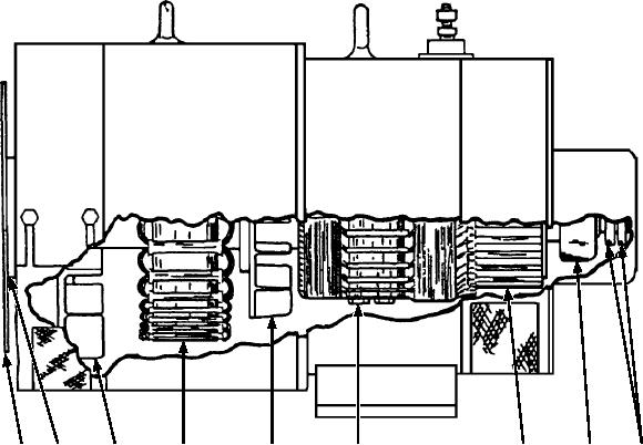
ASf07048
1. Driving disk
4. Ac generator field
7. Comutator
2. Coupling hub
5. Dc generator fan
8. Bearing assembly1234567
3. Ac generator fan
6. Dc generator armature
9. Slip rings
Figure 7-48.--Cutaway view of an NC-8A generator.
The high engine coolant temperature
wye-connected t o p r o d u c e 1 1 5 / 2 0 0 Va c . T h e
maximum output of the alternator is 168 amperes, 60
The low fuel supply
kVA. It is electronically protected from improper
voltage and frequency.
The low engine oil pressure
Protective System
A reset button is provided to return the fault locator
circuitry to the operating condition after the
The protective system is designed to prevent
malfunction has been corrected.
damage to the engine, generator, propulsion system,
and electrical systems as a result of a fault condition.
Overvoltage Relay
Circuit breakers provide overload protection for
The overvoltage relay is located in the electrical
the ac and dc generators.
control box. It is a sealed electronic unit designed to
An integral part of the protective system is the fault
protect the generator and the unit being serviced from
locator with its associated relays and fault-sensitive
damage due to excessive voltage. It is connected to
devices. The fault locator automatically shuts down or
each of the three phases of the generator output (K10,
idles the engine, deactivates the generator, opens the
fig. 7-49). The overvoltage relay works in conjunction
load contactors, and/or deactivates the propulsion
with the fault indicator assembly and the generator
system if a fault occurs. It is positioned on the
fault relay. If an overvoltage fault occurs, the relay
generator control panel; it enables you to determine
contacts close. This signals the malfunction to the fault
which of the following conditions activates the fault
indicator assembly. The fault indicator energizes the
locator's protective circuitry:
The ac over/undervoltage
to return to idle, and opens the ac output relay.
The overvoltage relay (fig. 7-50) continually
The over/underfrequency
samples all three phases of the ac generator output. The
The dc overvoltage
outputs are connected to terminals A, B, C, and N of the
7-40