
the PID circuit to change engine fuel flow to
correspond to increased or decreased acceleration.
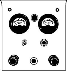
D. C. CONTROL
G EN. AMPS
G EN.VOLTS
DC POWER CONTROL AND DISTRIBU-
TION.--The dc generator is an aircraft generator with
an output of 28 volts dc and 500 amperes at a minimum
speed of 5,700 rpm and a maximum speed of 6,300
G EN. ON
DC POWER
rpm. The dc generator is located on the right side of the
speed increaser gearbox next to the ac generator. The
OFF
ON
OFF
dc generator supplies the voltage necessary to excite
ENERGIZED
the drive motor, which propels the power plant as well
as the voltage required for aircraft servicing.
DC SERVICE CABLE
The transistorized dc voltage regulator, with
ASf07044
Figure 7-44.--Dc control panel.
current limit and line drop compensation, regulates the
voltage of the 28-volt, 500-ampere dc generator by
statically switching the full generator output voltage
The remainder of the discussion of vehicle
back to its own field often enough and for long enough
propulsion refers exclusively to figures 7-43 and 7-44.
periods of time to maintain required excitation current.
The dc generator output voltage, which energizes
The inductive effect of the generator field causes the
the drive motor, is now controlled by engine speed
excitation current to remain virtually constant through
using accelerator rheostat R4, governor interface
any given cycle, even during the time when no voltage
control module E7, line filter E8, and governor control
is applied.
box/actuator E9. The higher the output voltage, the
faster the power plant moves. Accelerator rheostat R4
Prior to dc power distribution, the engine must be
and switch S29 are connected to governor interface
operating, the START/DRIVE-SERVICE POWER
module E7. The governor interface module routes the
switch S29 (fig. 7-43) must be in the SERVICE
signals from R4 and S29 through line filter E8 to
POWER position, and the DC POWER switch S5 must
governor control box/actuator E9.
be in the dc POWER position. The following is a
step-by-step explanation of how the dc distribution
The governor control box/actuator houses a
circuit works.
proportional-integral-differential (PID) control circuit
which is used to control the actuator output. The
The coil of the power control relay (within the
governor control box/actuator receives signals filtered
governor interface module) and the coil for the ac
by line filter E8 from accelerator rheostat R4, the
generator control relay K5 are energized by battery
magnetic pickup mounted on the flywheel housing,
voltage when S-29 is placed in the SERVICE POWER
and interface module reference speed pot R4. These
position. The electronic governor is receiving engine
signals are processed and compared, resulting in an
rpm feedback from the magnetic pickup at the
error signal, which is amplified through a gain circuit;
flywheel, and holding the diesel engine at
the output of the gain circuit is sent to the actuator shaft
approximately 2,550 rpm. This prime mover rpm
through the PID control circuit. This causes the
equates to 6,000 generator rpm (400 hertz). The field of
actuator shaft to rotate--the actuator converts the
the ac generator is connected to the ac voltage regulator
electrical signal received from the control box to an
VR1 through the closed contacts of generator control
angular mechanical output, which is translated along
relay K5.
the control rod to the engine fuel control rack. This
Placing the dc POWER switch S5 in the dc
adjusts engine speed by controlling the amount of fuel
POWER position energizes field control relay K11. B1
injected into the engine.
and B2 contacts of K11 close. The circuit between dc
The actuator returns a feedback signal to the
voltage regulator VR2 and the field of dc generator G2
control box, which compares the current output to the
i s n ow c o m p l e t e . B a t t e r y vo l t a g e , r e d u c e d t o
input from the magnetic pickup and the reference
approximately 1 Vdc by resistor R5, is fed through
speed setting. Once accelerator rheostat R4 changes
diode CR4 into the dc voltage regulator at pin C to
value (i.e., the accelerator pedal is pressed), the
boost the residual magnetism of the generator and
magnetic pickup senses the change in flywheel
rotation, and the output of the actuator is adjusted by
ensure buildup of output voltage. After the generator
7-36