
The engine starting circuit
ineffective because of the varying electrical loads. For
these reasons all MEPPs use some type of automatic
The vehicle propulsion circuit
governor. The NC-2A power plant uses two electronic
governors--the drive control module assembly and the
The dc power control and distribution circuit
engine governor assembly.
The ac power control and distribution circuit
Control of the engine speed is accomplished by an
electric torque motor that adjusts the fuel flow to the
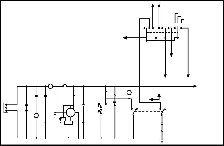
ENGINE STARTING CIRCUIT.--Figure 7-40
engine. The movement of the torque motor shaft is
is a simplified schematic of the NC-2A starting circuit,
controlled by the selected governor assembly. The
and figure 7-41 is a picture of the NC-2A control panel.
operation of the NC-2A is selected by positioning the
mode selector switch. With the mode selector switch in
Prior to starting the engine, MASTER SWITCH
the START/DRIVE position, the drive module
CB4 (fig. 7-40) must be closed, start cutout relay K21
assembly controls the torque motor and the speed of
must be energized (closing contacts B1 and B2), and
the dc generator.
START/DRIVE-SERVICE POWER switch S29 must
The engine governor assembly takes control of the
be in the START/DRIVE position.
torque motor when the mode selector switch is turned
Holding ENGINE START switch S14 in the start
to the output power position. The engine governor
position energizes auxiliary start relay K20. Start
solenoid L1 is now energized through the closed
maintaining it at 400 hertz, plus or minus 10 hertz.
contacts of relay K20 and in turn cranking motor B3 is
energized through the closed contacts of solenoid L1.
System Operation
Fuel shutoff solenoid L3 is also energized permitting
free flow of fuel to the engine and is held energized
The NC-2A system is broken down into four major
during unit operation through water temperature
interrelated circuits for ease of explanation. Those
switch S11 and engine oil pressure switch S15.
circuits are:
TO GOVERNOR
INTERFACE MODULE
SERVICE POWER
SERVICE BOOST
START/DRIVE
CBA
S29
1
34
67
9
10
12
24 VDC
2
5
8
11
TO DC POWER
CONTROL &
DISTRIBUTION
CIRCUIT
TO PROPULSION CIRCUIT
TO DC VOLTAGE
CB4
REGULATOR
M4
L3
OFF
M7
X1
A1
X1
A1
K19
K21
L1
K20
X2
X2
A2
START
NO
S15
A1
S19
+
+
K19
BT1
NO
A2
1
4
3
6
C
AUX
G3
-
BT2
B+ GRD
S11
S14
-
C1
2
J5
5
B3
F
0.1UF
200V
RD GRN
B1
V
F BLK
L1
L2
K21
C2
B2
VR3
0.1 UF
X1
200V
K20
X2
ASf07040
Figure 7-40.--Engine starting circuit.
7-33