ENGINE RPM
OIL
BATTERY AMMETER
WATER
RUNNING TIME
20
0
20 40 60
160 200
20
20
15
25
SERVICE PWR
120
40
0
80
40
240
30
10
SER
BOOST
35
5
START/DRIVE
0
40
CIRCUIT BREAKER
INTENSITY
PANEL
ENGINE
LIGHTS
VEHICLE MOTION
START
OFF
MASTER
FWD
RUNNING
REV
LIGHTS
SWITCH
LIGHTS
LOW FUEL
GEARBOX LOW
OIL PRESS
ASf07041
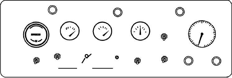
Figure 7-41.--Engine control panel.
After the engine fires, releasing ENGINE START
MOTION switch S9 in the FWD position and
switch S14 de-energizes relay K20, solenoid L1 and
depressing brake switch S7. Drive motor lockout relay
starting motor B3. Start cutout relay K21 is
K17 is now energized by battery voltage through limit
de-energized by voltage regulator VR3 when the
switch S4, brake switch S7, and blocking diode CR5.
engine reaches approximately 500 rpm. With the
Relay K17 is held energized during forward operation
engine operating, control of the engine rpm is
by battery voltage through START/DRIVE-SERVICE
maintained by the governor.
POWER switch S29, and its own closed contacts B1
and B2. Relays K13 and K14 are now energized by
Should an over speed condition occur
battery voltage through switch S29, closed contacts
(approximately 2,800 rpm) during starting or unit
K17, C1, and C2, and K18, A2 and A3, closing their
operation over speed switch S19 will close and
contacts A1 and A2 across the drive motor.
energize air lockout relay K19. Air shutoff solenoid L2
is now energized through the closed contacts A1 and
For reverse operation the VEHICLE MOTION
A2 of relay K19. After an over speed shutdown air
switch S9 is placed in the REV position and brake
shutoff solenoid L2 must be manually reset before
switch S7 is again depressed permitting reverse control
engine restart can be accomplished.
auxiliary relay K18 and reverse control relays K15 and
K16 to be energized. Contacts A1 and A2 of relays K15
Should a high engine temperature condition occur
and K16 are closed directing dc generator output
(approximately 200F), switch S11 will actuate and
voltage through drive motor B1 in the reverse
remove electrical power from fuel solenoid L3 causing
direction. Relay K18 is held energized during reverse
the engine to shut down.
operation by its own closed contacts B1 and B2.
Should a low oil pressure condition occur
Figure 7-43 is a simplified schematic of the engine
(approximately 10 psi), engine oil pressure switch S15
governor and dc power control circuit, and figure 7-44
will actuate and remove electrical power from fuel
is a picture of the dc control panel.
solenoid L3 causing engine to shut down.
Control of the MEPP speed during propulsion is
VEHICLE PROPULSION CIRCUIT.--For the
the same for forward or reverse operation. Safety
discussion of the vehicle propulsion circuit, refer to
switch S27 (fig. 7-42) must be held closed and the
figure 7-42, a simplified schematic of the propulsion
accelerator pedal depressed for motion. With the dc
circuit.
voltage regulator VR2 (fig. 7-43) isolated from the
Prior to vehicle propulsion, the engine must be
propulsion circuit, a control or biasing voltage must be
o p e r a t i n g , t h e d c p ow e r m u s t b e o n , a n d t h e
induced across the field of the dc generator to permit
START/DRIVE-SERVICE POWER switch S29 must
generator output. This is accomplished by depressing
be in the START/DRIVE position.
the accelerator pedal and closing limit switch S4 (fig.
7-42). Battery voltage, reduced by speed regulating
For forward operation drive motor lockout relay
resistor R1 (fig. 7-42) is induced across the dc
K17 and forward control relays K13 and K14 must be
energized. This is accomplished by placing VEHICLE
generator field through switch S29 (fig. 7-43).
7-34

