
9
9
8
A
VIEW
8
7
2
A
VIEW
A
10
7
2
A
1
10
1
3
4
5
6
ASf07061
5
6
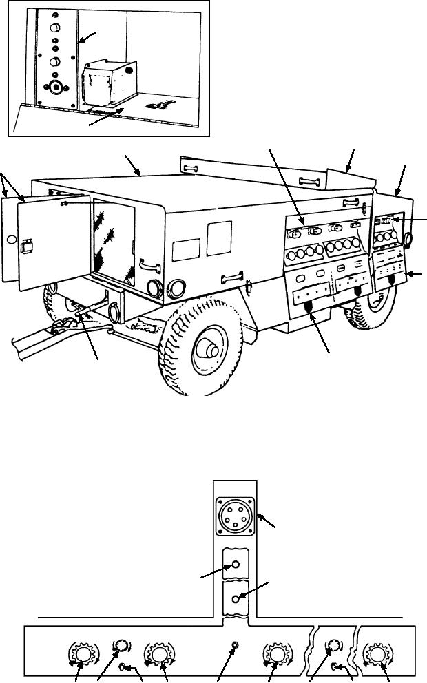
1.
Forward door, air exhaust
6. Parking brake control lever
2.
Dc input panel
7. Cover, control console
3.
Ac input panel
8. Storage compartment
4.
Cover, ac input panel
9. Circuit breaker panel
5.
Cover, dc input panel
10. Control console
Figure 7-61.--Load bank with access doors open.
CIRCUIT
CHECK
12
J-13
EXTERNAL
POWER
DC CONTROL PANEL
AC CONTROL PANEL
5
6
WIND
SWITCH
CLOSED
CONTROL CIRCUIT
INTENSITY
INTENSITY
VARIABLE 0-3.5 KW
VARIABLE E 0-55 AMPS
VARIABLE 0-55 AMPS
VARIABLE 0-3 K VAR
CREASE
CREASE
OFF
IN
IN
CREASE
CREASE
CREASE
CREASE
IN
IN
IN
IN
AC
DC
PANEL LIGHTS
PANEL LIGHTS
8
9
10
11
1
2
3
4
7
ASf07062
Figure 7-62.--Master control panel.
7-55