
3. Select the calculated total resistive load in KW
component factors: total (three-phase) KW,
single-phase KW, total KVAR, and single-phase
by placing the appropriate RESISTANCE
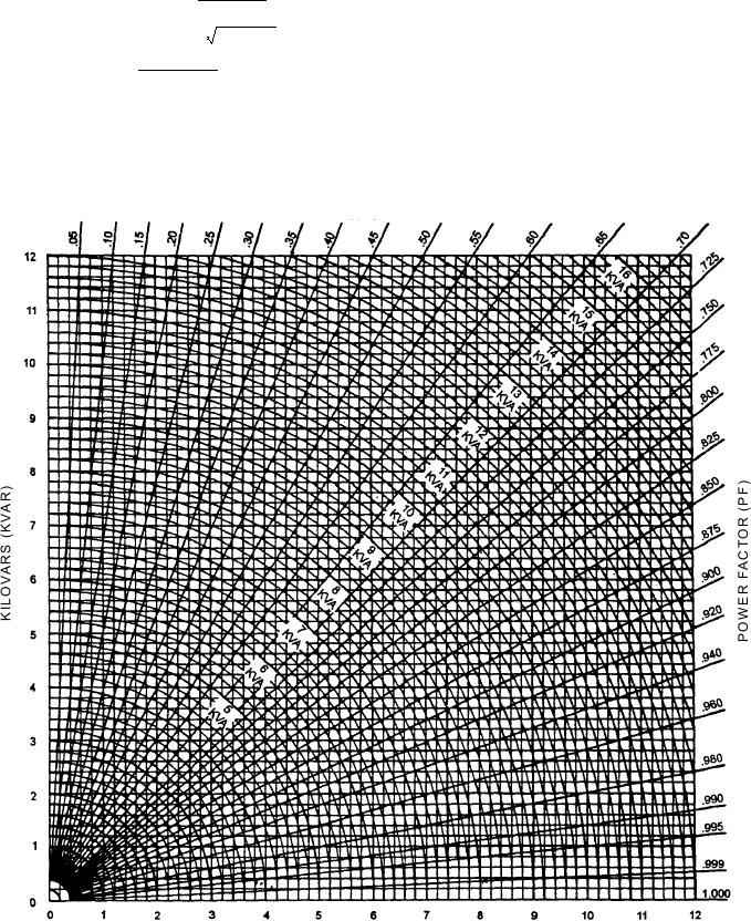
amperes (I1), from the formulas below or by
LOAD SELECTORS 3 PHASE KILOWATTS
referring to the chart in figure 7-65, (to obtain
toggle switches (20, 21, and 22, fig. 7-64) in the
approximate values for total KW and total
ON position.
KVAR).
4. Select the calculated reactive load in KVAR by
t o ta l K W = K VA x P F
placing the appropriate REACTANCE LOAD
total KW
SELECTORS 3-PHASE KILOVARS toggle
single-phase KW =
3
switches (16, 17, and 18, fig. 7-64) in the ON
t o ta l K VA R = K VA x 1 - ( P F )2
position.
KVA x 1,000
I1 =
5. Place the SHOCK LOAD switch (19, fig. 7-64)
3V
in the ON position and read the following
meters: POWER FACTOR meter (7, fig. 7-64),
where V is the voltage indicated by the
SINGLE-PHASE KW meter (9), and AC
SINGLE-PHASE VOLTS (L-N) meter (13, fig.
AMPS meter (12) to verify that the required load
7-64).
is being applied.
P O W E R FA C TO R ( P F )
K I L O WAT T S ( K W )
ASf07065
Figure 7-65.--Kilowatts (KW) chart.
7-64