NOTE 2
The centerdeck station is a part of the
control system in that it is a vital visual and
communications link between the catapult
officer and the control console.
(The control system on CV-68 and subsequent
carriers uses the ICCS and the central charging panel.
This control system is discussed in more detail later in
this chapter.)
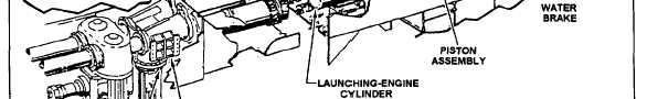
LAUNCHING ENGINE SYSTEM
The components of the typical catapult launching
engine system (fig. 4-3) are virtually the same on all
catapults. The major difference is the total length of the
launching cylinders, and, in the case of the C-13-2
catapult, the diameter of the launching cylinders (refer
to table 4-1).
As is shown in figure 4-3, the launching engine of
a steam catapult consists of two rows of slotted
launching (power) cylinders, cylinder covers, two
sealing strips, two steam piston assemblies, a shuttle,
two water brake cylinders, and the catapult trough
covers. Associated with the launching engine are the
digital endspeed indicator system, cylinder elongation
and expansion indicators, and trough heaters.
Launching Cylinders
Each catapult has two rows of launching cylinders
mounted parallel to each other in the catapult trough.
They are made up in sections, with the number of
sections determined by the overall length of the
catapult. The cylinder sections are bolted together at
their flanges (fig. 4-4) by means of long stud bolts,
spacers, and nuts.
Base pads are welded in the bottom of the catapult
trough at specified intervals to match the bearing pads
fastened to the cylinder bases. Shims are then used to
properly align each cylinder section, and then the
cylinder sections are secured to the trough base pads by
bolts and clamps, which prevent the lateral movement
of the cylinders while allowing smooth elongation of
the cylinders due to thermal expansion. Lubricator
fittings are provided for lubrication of the sliding
surfaces.
Figure 4-3.—Launching engine system (typical).
4-5