
Engine Control Amplifier
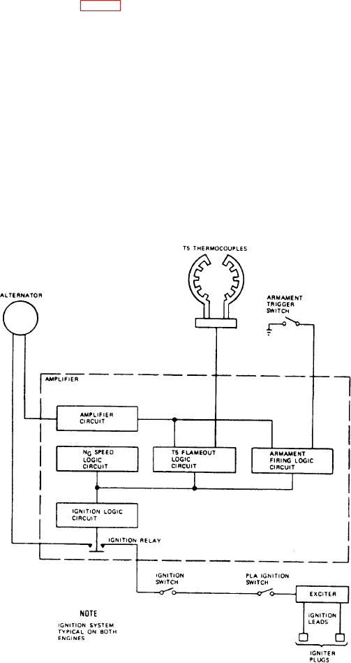
The engine ignition system (fig. 5-6) provides
the necessary electrical energy and control to begin
The engine control amplifier is the electronic
engine combustion during aircraft armament
control center of the engine. It controls the
firing and starting, and for automatic reignition
function of the ignition system as well as other
in case of engine flameout.
engine operational functions. The amplifier
mounts on the compressor section aft of the
Engine Ignition Exciter
engine front frame.
The engine ignition exciter is a dual-circuit,
Engine Ignition Leads and Igniter Plugs
dual-output unit that supplies a high-voltage.
high-energy electrical current for ignition. The
The ignition leads are high-tension cables,
exciter consists of a radio frequency interference
which transmit electrical current from the exciter
filter and two power, rectifier, storage, and output
to the igniter plugs. The igniter plugs mount in
elements. The exciter mounts on the forward part
the combustion chamber housing.
of the compressor section of the engine.
Figure 5-6.-Jet engine electronic ignition system.

