
to the y-coordinate. By looking at figure 7-31, you
detecting a positive acceleration. It also shows the
y-accelerometer detecting a negative acceleration
during this interval. If the vehicle maintains a
constant speed throughout the turn, the detected
acceleration results from a velocity change. This
change is due to a change in direction rather than
a change in speed. This acceleration is radial
(centripetal) acceleration (AR). The direction of
the radial acceleration is toward the center of the
turn and perpendicular to tangential velocity (VT).
Find coordinates (17.5, 17) in figure 7-30. If the
speed hadn't been constant during the turn, a
This acceleration would parallel the tangential
velocity (VT) vector and be normal (at a right
direction of the tangential acceleration would
depend upon whether the speed was increasing
or decreasing, positive or negative. If the
turning vehicle's acceleration is due to changes
in speed and direction, the accelerometers detect
the x and y components of the resultant of
the two accelerations.
Remember, when detecting acceleration of an
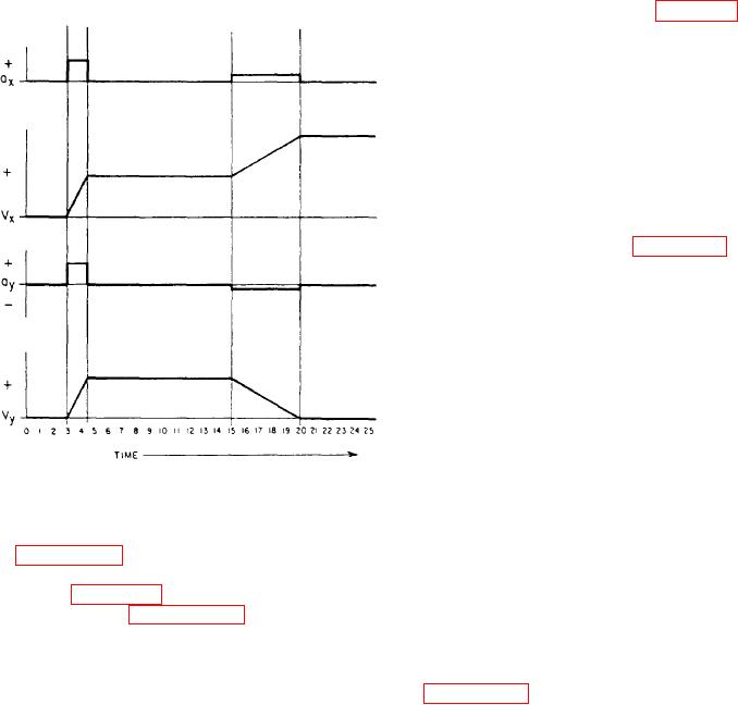
Figure 7-31.-Acceleration and velocity curves.
accelerating body, accelerometers detect only
the component of the resultant acceleration along
their sensitive axis. Accelerometers can't tell if the
Figure 7-31 is an illustration of a typical set
detected velocity change is due to a speed change
of acceleration and velocity curves from the INS
or a direction change or both, Nor does it matter
shown in figure 7-30.
what forces cause the velocity changes. The result
Referring to figures 7-30 and 7-31, the
is the same, provided the accelerometers maintain
operation of the plane inertial navigation system
correspondence with the coordinate axes.
is explained as follows: The vehicle aligns
Refer to the acceleration and velocity curves
(initializes) on the coordinate system with a
in figure 7-31. Notice the integration of the
displacement of 3 on the x and y axes. That is,
x-component of acceleration for the interval t15
both x and y displacement indicators read 3. At
to t20. It shows an increase in the x-component
time t3, the vehicle experiences an acceleration,
of velocity and, therefore, a corresponding
A, in a direction of 45 from the x-axis. The ac-
increase in displacement along the x-axis.
celerometers detect only that portion of the
Integration of the y-component of acceleration
acceleration that lies along its sensitive axis. This
over the same interval shows that the velocity goes
means the x-accelerometer detects the component
to zero at time t20. Therefore, the displacement
of acceleration along the x-axis. This is A cos a.
along the y-axis ceases to change. Hence at time
The y-accelerometer detects the component of A
t15, the displacement is (15, 15). At time t20, the
along the y-axis, which is A sin a. The vehicle
displacement is (20, 15) and at time t25, the
continues in a direction of 45 until time t15. At
displacement is (25, 15), etc.
this time it begins a turn to the right. Since sine
The INS just described navigates very well on
and cosine are equal at an angle of 450, the
a flat surface. However, navigation on the earth
displacements along x and y are equal at time t15.
requires a highly complex inertial system. The
This says x = 15 and y = 15. Also, it means the
earth, of course, is not flat, neither is it exactly
acceleration and velocity along the x-axis is equal
round. Its radius at the poles is less than its radius
to the acceleration and velocity along the y-axis.
at the equator. It also spins about its polar axis
At time tl5, the vehicle begins a right turn, it
and orbits around the sun. You must take all of
completes the turn at time t20. The new direction
these factors into account and correct them
is parallel to the x-coordinate and perpendicular
7-26