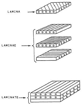
See figure 14-23.
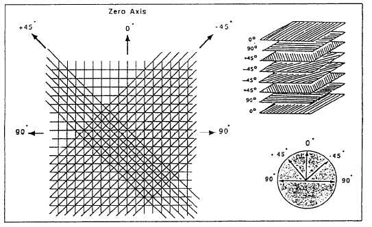
Drawings specify ply stacking
angles and the sequence of the lay-up. A standard
laminate orientation code is used to ensure
standardization in the industry. The orientation code
denotes the angle, in degrees, between the fibers and
the “X” axis of the part. The “X” axis is usually
spanwise of the part, or in the direction of applied
loads. See figure 14-24. The laminate ply orientation
or stacking sequence is denoted in brackets, with the
angle of each ply separated by a slash (/); for example,
[+45/–45/+45/-45]. Laminae are listed in sequence
from the first lamina to the last. The brackets or
parenthesis indicate the beginning and the end of a
code. The plus (+) and minus (–) angles are relative
to the “X” axis. Plus (+) signs are to the left of 0, and
minus (–) signs are to the right of 0. Adjacent laminae
of equal angles but opposite signs are identified as ±,
(±45
= +45, –45). The directional strengths and
stiffness of the laminate can be altered by changing
the ply orientation.
CATEGORIES OF COMPOSITE
MATERIAL DAMAGE
Figure 14-23.—Laminae stacking.
Advanced composite materials continue to be
increasingly popular with designers of new aircraft.
It is estimated that new airframes will be 75 percent to
Figure 14-24.—Standard ply orientation clock.
14-22