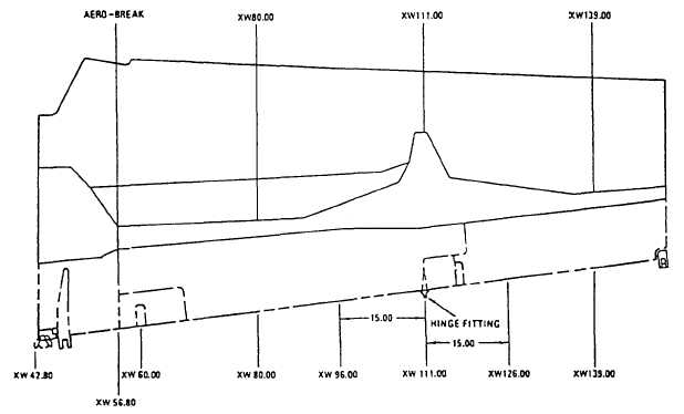
Figure 14-27.—Repair zones.
critical zones include leading edges of wings and
tails, forward nacelles and inlet areas, forward
fuselages, and overwing areas of the fuselage. The
least critical zones include trailing edges and aft
fuselage areas.
Repair Tools
Drill motors should be capable of speeds of 2,000
to 5,000 rpm. These drills should be equipped with
feed rate limiting surge controls to prevent backside
breakout caused by feeding the drill too fast and
excessive heat buildup from feeding the drill too slow.
Feed rates should not exceed 30 seconds per inch,
with 10 to 15 seconds per inch producing the best
results on graphite-epoxy composites. The drill
should be turning full speed prior to surface contact
and during withdrawal from completed holes. These
holes should be drilled slightly undersize and reamed
to the required size. The various types of drill bits
used for drilling composites are either twist, flat
fluted/spade/dagger, single flute, or piloted
countersink, and they are made out of carbide or
carbon steel.
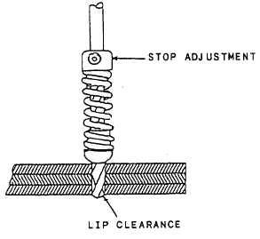
A drill stop (fig. 14-28) is an adjustable spring
damper that is attached to the drill bit shank. This
mechanically stops the drill at a predetermined depth
prior to exiting the material backside, thus reducing
backside breakout caused by the follow through.
Firm pressure is required to overcome this spring
tension for the drill to penetrate the laminates
backside.
Routers are high-speed, hand-held, portable
cutters used for removing damaged skin or core
materials. They are designed to operate on shop air at
Figure 14-28.—Drill stop.
14-27