engine. The radiator unit consists of a cylindrical
case containing two cooling coils of 1/4-inch
aluminum alloy tubing and a replaceable fuel filter
element. The utility system cooling coil is installed in
the right-hand end of the case; the flight control
system cooling coil and the filter element are installed
in the left-hand end, as shown in figure 7-28. The
case ends contain fittings for connecting fuel hoses.
Two threaded bosses, which are welded to the cooling
coil ends, serve to connect the hydraulic lines for each
system. During normal operation, hydraulic fluid
returning to each reservoir is directed through its
applicable system cooling coil, where sufficient heat
is transferred to the engine fuel to maintain the
hydraulic fluid at less than 200°F.
Should the cooling coils become clogged, each
system is equipped with a bypass relief valve, which
opens and bypasses fluid around the coil and directly
to the reservoir.
Fin Tubing Types
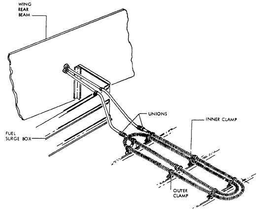
Some aircraft use fin tubing for cooling hydraulic
system fluid. Hydraulic fluid coolers are mounted
internally in the wing inboard fuel tanks. As shown in
figure 7-29, each cooler is an assembly of fin-walled
tubing, two unions, and mounting supports. Fluid
enters the inlet coupling and is passed through the
fin-walled tubing, which acts as a heat exchanger, and
is directed to the outlet coupling for return to the
system reservoir. The heat of the fluid passing
through the coolers is absorbed by both the fin-walled
tubing and the fuel.
NOTE: The fuel level in the inboard tanks
must be maintained at a specific level to
ensure adequate cooling of the fluid.
MANIFOLDS
A manifold is a hydraulic component used to
conserve space and permit ease of unit removal and
replacement. It also provides a means where common
fluid lines may come together and be distributed to
other subsystems.
Manifolds are used in various
types of installations, depending upon the needs of the
system.
Figure 7-29.—Fin tubing assembly Installation.
7-30