brake-lever rod on the top of the instrument is moved
to the closed position. This locks the pointer in place.
Then, the lever assembly is released and the
instrument removed from the cable with the pointer
locked in position. After the reading has been noted,
the brake-lever rod is moved to the open position, and
the pointer will return to zero.
The tensiometer, like any other measuring instru-
ment, is a delicate piece of equipment and should be
handled carefully. Tensiometers should never be
stored in a toolbox.
Temperature changes must be considered in
cable-type systems since this will affect cable
tensions. When a temperature is encountered that is
lower than that at which the aircraft was rigged, the
cables become slack because the aircraft structure
contracts more than the cables. When temperatures
higher than that at which the aircraft was rigged are
encountered, the aircraft structure expands more than
the cables and tension is increased.
The cables in any cable linkage system are rigged
according to a temperature chart that is contained in
the applicable maintenance instructions manual. This
chart will give the proper tensions for the various
temperature changes above and below the
temperature at which the system was rigged.
Rig Pins
Rig pins are used in rigging control systems.
Figure 9-24 shows a rigging pin kit used on one of the
Navy’s aircraft. As you can see, rig pins may come in
various sizes and shapes and may be designed for one
or many installations. You should refer to the specific
maintenance instructions manual for use and selection
of rig pins.
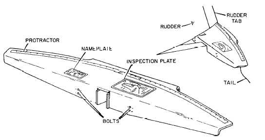
Throwboards
Throwboards are special equipment used on
specific aircraft for accurate measurement of control
surface travel. See figure 9-25. Each throwboard has
a protractor scale that indicates a range of travel in
degrees. Zero degrees normally indicates the neutral
position of the control surface. When the throwboard
is mounted and the control column or stick is in
neutral, the trailing edge of the control surface should
be aligned to zero. As the control column or stick is
moved to its extreme limits, you can read the
corresponding degree indication on the throwboard.
If the travel of the control surface is out of limits, you
should adjust cables, push-pull rods, and control limit
stops to obtain the correct control surface travel.
When you are inspecting and rigging control surfaces,
the specific maintenance instructions manual should
be consulted.
Figure 9-25.—Typical throwboard used for rigging rudder and rudder tab controls.
9-31