Drum Loader Assembly MHU-133/E32K
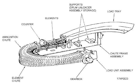
The drum loader assembly (fig. 7-14) is used to
load the transporter with unlinked ammunition. The
drum loader assembly places the unlinked rounds into
the conveyor elements, which carry the rounds to the
load unit assembly. The load unit assembly removes the
rounds from the elements and places them into the
retainer partitions in the entrance drum cover. You can
time the load unit assembly by inserting a pin through
the cover, through a hole in one of the gears, and into a
hole in the housing. The drum loader consists of a load
tray (onto which the rounds are placed), a belt of
elements, two chutes (which control the rounds and
elements when they are between the tray and the load
unit), and a load unit assembly. The load unit assembly
contains two gear-driven sprocket assemblies that
transfer the rounds from the belt of elements to the
drum cover partitions and a gearbox that drives the
drum loader assembly. The gearbox can be driven by a
1/2-inch drive hand crank, making it easier to transport
the rounds. A resettable counter indicates the number of
rounds that have been loaded into the transporter.
Drum Unload Assembly MHU-132/E32K
The drum unload assembly (fig. 7-15) removes
rounds and/or spent cases from the transporter and
separates them from each other. The drum unload
assembly contains a gear-driven sprocket that removes
the rounds/spent cases from the drum exit cover and
places them on a tray. The tray has a hole that lets spent
cases drop through while the rounds must travel the
length of the tray. You can time the drum unload
assembly by inserting a pin through the cover, through a
hole in one of the gears, and into a hole in the housing.
Conveyor System MHU-130/E32K
The conveyor system (fig. 7-16) transports rounds
from the transporter to the aircraft system. It
simultaneously transports spent cases and cleared
rounds from the aircraft system to the transporter. The
conveyor system is mounted on the top of the
transporter. It consists of a chute support assembly,
three ammunition chutes, two element chutes, an exit
unit assembly, an interface unit assembly, an entrance
unit assembly, and a drum drive assembly that is driven
by a flexible drive shaft.
CHUTE SUPPORT ASSEMBLY.—The chute
support assembly is a rigid structure that supports other
units. It also provides stowage for other units when they
aren't in use. A portion of the chute that is required for
the control of spent cases and elements is a rigid
wire-form chute. This chute is part of the chute support
assembly. Casters are provided on one end of the chute
support assembly to aid in moving the assembly when it
is not mounted on a transporter.
CHUTES.—The ammunition and element chutes
control the elements and rounds or spent cases when the
system is operating. The chutes are flexible enough to
permit interconnection of the various units.
7-12
Figure 7-14.—Drum loader.