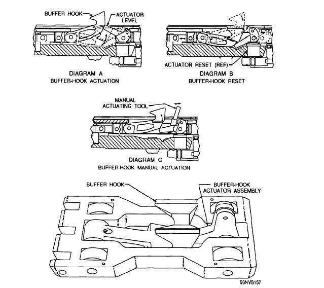
Figure 5-11.—Nose-gear-launch slide assembly.
position to engage the aircraft holdback bar (see
diagram A, fig. 5-11). As the aircraft continues
forward, the holdback bar engages the buffer hook.
The moving aircraft pulls the slide assembly
forward, thus pulling the buffer-cydinder piston rods
forward out of the buffer cylinder assembly.
Hydraulic resistance within the buffer cylinder
assembly decelerates the aircraft. When the aircraft
stops, it is in position for launch bar/catapult
spreader assembly hookup. After launch, the piston
rods are retracted into the buffer cylinder assembly
automatically. As the slide assembly moves aft, a
level through an opening in the track into the deck
housing.
NOSE-GEAR-LAUNCH ACTUATOR
RESET ASSEMBLY
The actuator reset assembly (fig. 5-12), which
resets the buffer hook, causing it to drop below deck
at the end of the buffer-cylinder-assembly retract
stroke, is located below the slide assembly in the
deck housing. The assembly consists of a cylindrical
housing, slider, slider actuating spring, and retainer.
The slider contains a Stellite surface to lessen the
tooth in the actuator assembly contacts the extended
effects of wear during
reset-assembly slider (see diagram B, fig. 5-11),
slide-assembly reset roller,
causing the actuator lever to rotate down. This
body to prevent corrosion.
action permits the buffer hook to drop below deck
5-13
contact with the
and a chrome-plated
Grooves machined in