designed to act as a single spring by means of rods
(3) that pass through each set of springs and end in
eyed terminals (6). The inboard ends of the rods
are bolted to clevises (2), which are welded to an
equalizing plate (l).
The plate has a threaded
adjustable rod that is secured to the ship’s structure
to hold the inboard ends of the spring unit. The
outboard ends of the rods are bolted to a similar
plate, which has a welded clevis outboard, through
which is bolted the eyed terminal of the
counterbalancing spring cable. The cable (7) runs
through two sheaves and is then bolted through its
terminal to the actuator arm of the barricade
stanchion, below the point of attachment for the
cylinder.
When the stanchion is lowered by the cylinder,
the sets of springs are uniformly compressed and
resist the force of the descent, and cushions its fall
against the deck. Raising the stanchion slackens the
spring cable and decompresses the spring, but this
release of compression has no appreciable effect on
raising the stanchion.
STANCHION LATCH
Stanchion latches are used to secure the
stanchions to the deck in their DOWN position.
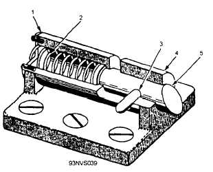
Stanchion latches (fig. 3-39) are spring-loaded
latches bolted to the subdeck and provided with a
slotted frame, designed to allow the latch (5) to bc
retracted against the force of a spring (2), and
turned to lock the latch open. When the stanchion
1. End plate
4. Body
2. Spring
5. Latch
3. Pin
Figure 3-39.—Stanchion latch assembly.
is lowered, the latch may be engaged in a hole
provided in the stanchion, and a spring will hold the
latch in.
POWER PACKAGE
The power package (fig. 3-40) provides and
maintains the fluid pressure required by the
hydraulic cylinders to raise and lower the barricade
stanchions. It consists of a base weldment, gravity
tank assembly (7), control panel assembly (8),
accumulator (1), motor controller (9), pump (2),
electric motor, electrical system, and piping system.
The gravity tank assembly has a capacity of
approximately 100 gallons and is the fluid reservoir
in the power package assembly. Displaced fluid
from the cylinder assemblies is returned to the
gravity tank, and from there it is pumped back to
the accumulator. The gravity tank is welded steel,
closed at the top and bottom by flat plates. The top
cover plate has an access hole, which is covered by
a cap plate and gasket held in place by bolts.
Tapped bosses welded to the cap plate are for
breather vents. A Iiquid-level gauge is connected to
the side of the gravity tank. An indicator plate is
attached to the tank at the level gauge to show the
proper fluid level.
The control panel assembly (fig. 3-41) is
attached to the gravity tank by four bolts.
The panel consists of the panel frame (1), two
piping support brackets (9), accumulator pressure
gauge (6), pressure sensing switch (7), gauge valve
(3), air-charging valve (5), vent valve (2), air supply
valve
(4), caution plate (8), and operating
instruction plate (10). Necessary copper tubing and
sil-braze fittings
connect the panel to the
accumulator assembly, to a ship’s exhaust line, and
to the ship’s high-pressure air supply line. The
accumulator pressure gauge (6) is used to indicate
pressures ranging from 0 to 2,000 psi in the
accumulator.
The pressure-sensing switch (7) is a piston type,
contained in a splashproof housing. It is connected
to the pressure line from the accumulator with a
threaded adapter and a coil of tubing between the
adapter and tee in the pressure line. The function
of the pressure-sensing switch is to maintain
accumulator pressure between 1,250 psi and 1,500
psi. It does this by opening or closing to stop or
start the pump motor. The pressure switch operates
3-42