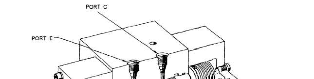
Figure 4-33.—Exhaust-vaIve hydraulic lock valve.
valve is locked in this position by pressure from port A
LINEAR AND ROTARY RETRACTION
acting on the larger working area of the lock valve
piston.
STEAM CUTOFF PRESSURE-SWITCH
INSTALLATION
The steam cutoff pressure-switch installation (fig.
4-34) is located at a point in the catapult power stroke
determined during the catapult certification program.
Flexible tubing connects the steam cutoff pressure
switch assembly to a port in one of the launching
cylinders. During a launch, the pistons pass the port,
allowing
steam to flow into the steam cutoff
pressure-switch installation and energize the LAUNCH
COMPLETE relays. These relays initiate closing of the
launch valves, opening of the exhaust valve, and the
subsequent automatic advancing of the grab. The steam
cutoff pressure-switch installation must de-energize the
LAUNCH COMPLETE relays before the catapult can
complete the interlock circuit for the next launch cycle.
The steam cutoff pressure-switch assembly is housed in
an intrusion-proof enclosure outside the trough. The
steam cutoff pressure-switch assembly contains two
pressure switches, a disk orifice, and a steam manifold,
which directs steam pressure from the flex hose to the
switches. The switches are nonadjustable, and the
contacts close at approximately 20 psi and open at
approximately 10 psi.
SYSTEMS
The function of both the linear and the rotary
retraction engines is to hydraulically control the
movement of the grab and to maneuver the shuttle
forward and aft when slow movement is required.
Normally, the engines are located directly below the
flight deck in close proximity to the launching engine
so excessive cable reeving and hydraulic lines and
piping are not required.
LINEAR RETRACTION ENGINE
Essentially, this system consists of the retraction
engine
cylinder and piston; the main hydraulic
accumulator; air flasks; the grab; the cables, which
couple the grab to the retraction engine; the crosshead
sheaves; cable equalizers; associated valves; and
electrical controls and piping. The general arrangement
of a linear retraction engine is shown in figure 4-35.
DRIVE SYSTEM
As shown in figure 4-36, the linear retraction
engine drive system consists of a grab, two advance
cables, two retrieving cables, an advance cable
equalizer, a retrieving cable equalizer, a crosshead, and
the various sheaves. The drive system operates in
conjunction with the retraction engine and the hydraulic
4-26