exhaust valve from opening until the launching valve is
closed and the keeper valve piston is shifted.
HYDRAULIC-LOCK-VALVE PANELS
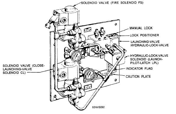
There are two hydraulic-lock-valve panels, one for
the launching valves (fig. 4-30) and one for the exhaust
valve (fig. 4-3 1). The launching-valve hydraulic-lock-
valve panel consists of two air-solenoid valves, the
hydraulic lock valve, the launch pilot latch solenoid,
and piping connections. The launching-valve hydraulic
lock valve (fig. 4-32) provides a hydraulic lock to hold
the launching-valve control valve in the FIRED position
until launching is completed or until the launching-
valve emergency cutout valve is placed in the EMER-
GENCY position, by controlling the flow of fluid to the
launching-valve control valve.
The launch pilot latch solenoid controls a plunger
that prevents the lock valve from being shifted to the
FIRED position unless the catapult control system is in
the FINAL READY phase of operation. (A manual lock
screw [fig. 4-32] is provided to secure the valve during
nonoperational periods.) When the catapult FIRE circuit
is energized, the fire air-solenoid valve directs air
pressure to shift the lock valve to the fired position.
This causes pressurized fluid to be directed from port A
through port B to the launching-valve control valve, the
keeper valve, and port D via the launching-valve
emergency cutout valve. Fluid pressure in port D
provides a hydraulic lock to prevent the valve from
shifting. When the catapult LAUNCH COMPLETE
circuit is energized, the close launch valve air-solenoid
directs air pressure to again shift the lock valve, venting
port D to gravity and directing pressurized fluid from
port A through port C to the launching-valve control
valve and closing the launching valves. (During a
HANGFIRE condition, port D is vented and port C is
pressurized when the launching-valve emergency cutout
valve is placed in its EMERGENCY position, ensuring
that the launching valves remain closed.)
The exhaust-valve hydraulic-lock-valve panel
consists of the exhaust-valve hydraulic lock valve, two
air-solenoid valves, and piping connections (fig. 4-31).
The exhaust-valve hydraulic lock valve (fig. 4-33)
opens and closes the exhaust valve by controlling the
flow of hydraulic fluid to the exhaust-valve actuator.
When the exhaust-valve open solenoid is energized, air
pressure is directed to the opening side of the lock
valve, causing it to shift. This allows fluid to flow from
port A, out port B, through the keeper valve, and into
the opening chamber of the actuator. Fluid also flows
from port D to lock the valve in the OPEN position.
When the exhaust-valve closed solenoid is energized,
air pressure shifts the lock valve to the closed position,
allowing fluid to flow from port A, out port C, and into
the closing chamber of the exhaust-valve actuator. The
Figure 4-30.—Launching-valve hydraulic-lock-valve panel.
4-24


