CSV assembly, refer to technical manual NAVAIR
51-15 ABE-1.
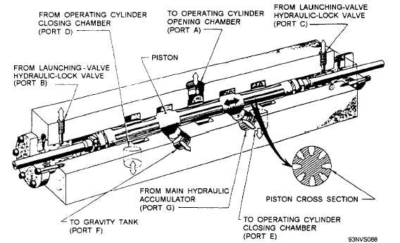
Launching-Valve Control Valve
The launching-valve control valve opens and closes
the launching valve assembly by controlling the flow of
fluid to the assembly. (See fig. 4-26.) It consists of a
steel body containing a sliding piston and five main
ports. As the launching valves go through their opening
and closing cycles, fluid is being directed to the
operating chambers by the action of the sliding piston,
lining up the ports and allowing pressurized fluid to
enter one chamber while venting the other chamber to
gravity. The piston has extensions that protrude from
each end of the valve body. The purpose of these
extensions is to give a visual indication of the position
of the control valve. Pressurized fluid used to shift the
control valve is supplied through a cam-operated pilot
valve on C-7/C-11 catapults and the launch valve
solenoid-operated hydraulic lock valve on C-13
catapults.
Butterfly Exhaust Valve
The butterfly exhaust valve consists principally of
a valve body, a disc, and a hydraulic actuator (fig.
4-27). The hydraulic actuator opens and closes the
valve. When hydraulic fluid from the exhaust-valve
hydraulic lock valve enters the opening port, the piston
moves to open the butterfly valve. Fluid entering the
closing chamber through the closing port acts on the
piston to close the valve. A limit switch is mounted on
the side of the exhaust valve. When the exhaust valve
is closed, the limit switch is actuated by a cam attached
to the shaft, and when the exhaust valve opens, the cam
rotates to the exhaust position and the limit switch is
released.
Pressure-Breaking Orifice Elbow
The pressure-breaking orifice elbow (fig. 4-28)
prevents a buildup of steam pressure behind the
launching engine pistons when the launching valves are
closed. Any steam, which may leak through the closed
launching valves when the exhaust valve is closed, is
permitted to escape through the pressure-breaking
orifice. This prevents the steam from entering the
launching cylinders, thus keeping the launching engine
pistons from moving forward before the catapult is
fired. The pressure-breaking orifice elbow is located
between the launching valves and the exhaust valve.
Keeper Valve
The keeper valve (fig. 4-29) is actuated by
hydraulic fluid from the launching-valve hydraulic lock
valve. The keeper valve prevents the exhaust valve from
opening while the launching valve is open. When the
launching valve opens, the piston of the keeper valve
shifts and blocks the flow of hydraulic fluid to the
exhaust valve hydraulic actuator. This prevents the
4-22
Figure 4-26.—Launching-valve control valve.