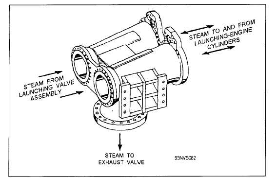
Figure 4-20.—Thrust exhaust unit.
prevents aft expansion of the launching engine
cylinders.
The thrust exhaust unit connects the
launching valves and the exhaust valve to the launching
engine cylinders.
Launching Valve Assembly
The launching valve assembly (fig. 4-21) consists
mainly of a steam valve assembly, a hydraulic cylinder
assembly, an operation control assembly, and the
launching valve stroke timer electrical installation. A
closed plate and an open plate are located on the
operation controls frame and an increment plate is
located on the operation controls crosshead. The
position of the valve can be determined by the
relationship of the increment plate to the closed and
open plates.
Steam Valve
The steam valve (fig. 4-22) admits and shuts off the
flow of steam to the launching engine cylinders during
catapult operations. With the valve in the CLOSED
position, two plugs in the valve are in full contact with
the valve body seats, providing a tight seal. When the
valve is opened, the plugs are moved away from the
valve body seats and rotated 90°. In the OPEN position,
the circular openings in the plugs are in line with the
valve body passages.
Hydraulic Cylinder Assembly
The hydraulic cylinder assembly is connected to the
operation control assembly (fig. 4-23). The cylinder
assembly is actuated by pressurized hydraulic fluid to
open and close the steam valve assembly. When
pressurized fluid is applied to port E, the piston moves
to the opposite end of the cylinder to open the steam
valve. The rate of movement of the piston is faster at
the beginning of the stroke, because of the effect of the
metering rod. At the beginning of the opening stroke,
fluid flows out of port A and port B. When the piston
has moved approximately 1 inch into the cylinder, the
metering rod shuts off the flow of fluid from within the
cylinder to port B. At the end of the opening stroke, the
orifice snubber controls the escape of fluid from the
cylinder. When pressurized fluid is applied to port A,
the piston moves toward the opposite end of the
cylinder to close the steam valve. At the end of the
closing stroke, the tapered end of the piston rod enters
the flange. This prevents the moving parts from
slamming to a stop and possibly being damaged.
Operation Controls Assembly
The operation controls assembly is attached to the
bottom of the steam valve assembly (fig. 4-24). The
assembly provides vertical movement needed for seating
and unseating the steam valve plugs and rotational
4-18


