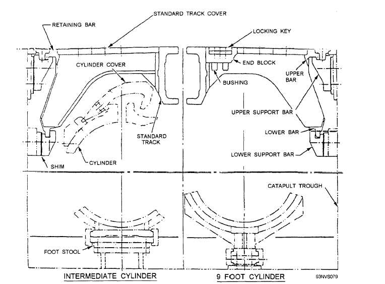
Figure 4-17.—Typical catapult trough cross section.
and the 8-foot to 10-foot-long forward covers (see
fig. 4-18). The 6-foot-long aft trough cover incorporates
a removable access plate to facilitate maintenance
procedures. The forward pair of trough covers is
provided with a 53-inch-long splash bar, which is
inserted in the slots of the upper track flange of these
covers. The trough covers are supported by the upper
and lower support bars, which are mounted on the
trough side walls. Each cover is individually keyed to
the upper support bars. The locking keys assure smooth
shuttle load transition between covers and restrain the
UP and DOWN movement between the cover ends. The
trough covers are held in place with retaining bars.
STEAM SYSTEM
The catapult steam system (fig. 4-19) consists of the
steam fill valves, dry-steam receivers or wet-steam
accumulator, the launching valves, the exhaust valve,
the pressure-breaking orifice elbow, and the steam
manifold. Associated with the steam system are the
capacity selector valve, launching valve-control valve,
exhaust valve keeper valve, launch complete steam
pressure cutoff switch installation, and the external
steam preheating system.
The steam fill valves control the flow of steam from
the ship’s boilers to the dry-steam receiver or wet-steam
accumulator. A steam blowdown valve is used to reduce
excess steam pressure or completely blow off steam
pressure when required. All steam fill and blowdown
functions are controlled from the catapult main control
station.
The thrust exhaust unit (figs. 4-19 and 4-20)
anchors the aft end of the launching engine and
4-16