b. Work the wire helix (spiral) down and off
the coupling end.
c. Remove the coupling end.
d. Remove the wire helix.
3. Make sure the hose is squared up, and mark the
hose for cutting, using the taper sleeve as a guide.
After marking, remove the taper sleeve.
4. Cut fabric-reinforced hose with a sharp knife
wetted with fresh water. Cut wire-reinforced hose with
a new or sharp hacksaw with fine teeth. Insert a round
wood plug into the hose to eliminate the danger of
loosening the inner liner or damaging the wire rein-
forcement while cutting.
coat of barrier.
5. Paint the freshly cut hose end lip with a light
coat of zinc chromate primer to provide a moisture
barrier.
6. Slide the external taper sleeve back on the hose.
7. Slide the wire helix on and position it about 6
inches down from the end of the hose.
8. Insert the coupling end into the hose, ensuring
the hose is bottomed at the lip of the coupling end.
9. Work the wire helix up and into position over
the inserted part of the coupling end. Be careful not to
overexpand the wire helix.
10. Slide the taper sleeve into position and screw it
tightly to the coupling end.
11. Hydrostatically test the hose as instructed in
the appropriate MRC.
12. Cut the continuity wire 10 to 12 inches longer
than the hose, to compensate for hose stretch.
13. Reinstall the continuity wire and spiders.
Check for electrical contact between the contact
buttons at the hose ends, using an ohmmeter.
Maximum allow-able reading is 40 ohm.
14. Upon reinstallation on a station, flush the hose
until an acceptable sample is obtained.
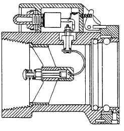
QUICK-DISCONNECT
COUPLING (QDC)
The quick-disconnect coupling (fig. 5-14) is de-
signed to provide the means of attaching the fuel
nozzle to the hose. It also contains the switch to
energize or de-energize the SOPV. When operating the
quick-disconnect coupling, don’t jam the switch, and
don’t drop the coupling on the deck.
The quick-disconnect coupling has a female thread
on one side to fit the male threads of the hose. The
other end has a female ball bearing quick-release that
receives the male end of the nozzle adapter.
NOZZLE ADAPTER
The flange side of the nozzle adapter is bolted to
the nozzle. The male end opening provides a means of
installing a 100-mesh strainer inside the nozzle as-
sembly. The strainer is held in place by a snap ring
that fits into a recessed groove inside the male end.
PRESSURE FUELING
NOZZLE
The pressure fueling nozzle connects to all NATO
military aircraft and is designed to provide a leak-proof
seal between the nozzle and the aircraft for high-
capacity fueling operations. This includes sup-plying
fuel under pressure to aircraft, and removing fuel by
suction from aircraft.
The pressure fueling nozzle is attached to the hose
by the nozzle adapter and quick-disconnect coupling.
The nozzle outlet attaches solidly to the aircraft refu-
eling adapter. The nozzle is secured to the aircraft by
aligning the slots in the nozzle with the lugs on the
aircraft adapter, pressing the nozzle firmly against the
aircraft adapter, and rotating the collar clockwise until
the internal stops are contacted.
The JC Carter D-1 and MD-1 are the pressure
fueling nozzles most widely used in the Navy.
Figure 5-14.—Quick disconnect coupling with
toggle switch.
5-13