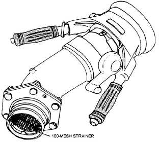
The MD-1 (fig. 5-15) is the newer nozzle and will
eventually replace all D-1 nozzles. Although physi-
cally similar, they differ internally, as the collar on
the MD-1 nozzle swivels independently of the body.
On the D-1 nozzle, the body and collar are one unit.
Because the MD-1 is scheduled to become the stan-
dard pressure nozzle used in the fleet, it is the only
one discussed here.
The MD-1 pressure fueling nozzle consists of
four major components. They are the collar assembly,
the nose seal assembly, the body, and the valve oper-
ating linkage.
Collar Assembly
The collar assembly holds the dust cover and the
bumper. The dust cover is used to keep dust, dirt, and
moisture out of the nozzle. The bumper is to provide
additional protection to prevent accidental damage to
the nozzle. The collar is attached to the body by 49
ball bearings.
Nose Seal Assembly
The nose seal assembly acts like a modified O-
ring to seal the nozzle to the aircraft refueling
connection and prevent leakage at the connection. It
is made of metal and an O-ring type material. It also
provides a housing for the poppet.
Figure 5-15.—MD-1 Pressure fueling nozzle
with nozzle adapter and strainer.
Body
The body houses the actuating linkage, indexing
pins, collar lock pin, and the collar lock pin spring. It
also has an opening to connect the sample connection
and another opening to connect the actuating lever.
The bottom of the body is attached to the inlet elbow
by 39 bearings. Leakage between the body and other
attached parts of the nozzle is prevented by O-rings.
Valve Operating Linkage
The valve operating linkage connects the actuat-
ing lever to the poppet. When the actuating lever is
rotated up and forward, the linkage pushes out the
poppet and opens the nozzle. When the actuating
lever is rotated backward and down, the linkage pulls
the poppet back into the nose seal assembly and
closes the nozzle.
The poppet is made of Teflon®-coated cast alumi-
num. A shroud on the bottom of the poppet eliminates
turbulence while fueling. The nozzle poppet pushes
on the aircraft fueling adapter poppet when opening,
thereby opening the aircraft fueling adapter.
GRAVITY (OVERWING)
FUELING NOZZLE
The gravity fueling nozzle (fig. 5-16) is manually
controlled. Like the pressure refueling nozzle, it is
attached to the end of a fuel hose by a nozzle adapter
and quick-disconnect coupling. The nozzle outlet is
inserted directly into the fuel tank. The nozzle is
actually a valve for controlling the rate of fuel flow,
and it closes automatically when hand pressure is
released.
When you move the control lever toward the noz-
zle handle, fuel is allowed to flow through the nozzle.
A dual valve in the nozzle allows a gradual opening
or closing of the nozzle.
The control lever presses against the valve stem
and lifts a small valve disk that is held against its
seat by a compression spring. When you open the
smaller valve, you avoid a sudden flow of fuel (known
as cracking the valve). After cracking, the continued
action of squeezing the handle depresses the valve
stem farther, and a shoulder on the stem meets the
large disk assembly, opening the valve fully. In clos-
ing the nozzle, the operation is reversed, and the
larger valve disk closes first. The small stream still
coming through the valve relieves the stress on the
hose, which results if the complete flow is suddenly
stopped. Fully releasing the control lever closes the
5-14