
PROPELLERS
The propeller converts the power output of the
engine into forward thrust to move the aircraft
through the air. A propeller is essentially a
"rotating wing, " or airfoil. When the aircraft
engine turns the propeller, relative motion is
developed between the wing-like propeller blades
and the air. As it pulls itself through the air, the
propeller carries along anything that is attached
to it, within the limitations of the power
developed. The faster the propeller spins, within
certain limits, the greater the resulting pull or
thrust.
BASIC PROPELLER PARTS
There are different propeller manufacturers
and many varied designs. These designs include
the experimental multicurved blade for propellers.
All propellers have the same basic parts. Terms
for the parts of one propeller are applicable to
other propellers. The basic parts of a propeller
are as follows:
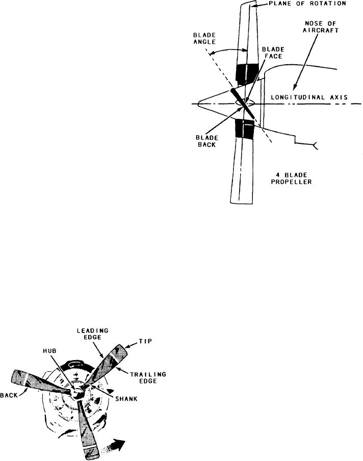
1. BLADE. One arm of a propeller from the
Figure 8-9.-A four-blade propeller.
butt to the tip. Propellers usually have two or
more blades. See figure 8-8.
4. SHANK. The thickened portion of the
2. BLADE BACK. The surface of the blade
blade near the hub of the propeller. The shank
as seen by standing in front of the propeller.
See figures 8-8 and 8-9.
is sometimes referred to as the root. See figure 8-8.
3. BLADE FACE. The surface of the blade
5. TIP. The portion of the blade furtherest
as seen by standing directly behind the propeller.
from the hub. See figure 8-8.
See figure 8-9.
6. HUB. The central portion of the propeller
that is fitted to the propeller shaft, securing the
blades by their roots. See figure 8-8.
7. LEADING EDGE. The forward or
"cutting edge" of the blade that leads in the
direction the propeller is turning. The other edge
(rear edge) is called the TRAILING EDGE. See
figure 8-8.
8. PROPELLER RETAINING NUT. The
nut that locks the propeller hub to the propeller
shaft. It is part of the propeller rather than the
engine.
9. BLADE STATIONS. These are reference
lines, usually designed as measurements, made
from the hub. These lines are numbered and locate
positions on the propeller blade. They are usually
designated at 6-inch intervals. The first station is
Figure 8-8.-Propeller basic parts.
8-9