
The turboprop fuel control and the propeller
a predetermined schedule. Below the flight idle
power lever position, the coordinated rpm blade
governor are connected and operate in coordina-
angle schedule becomes incapable of handling the
tion with each other. Together they establish the
engine efficiently. Here the ground handling or
correct combination of rpm, fuel flow, and
propeller blade angle to create sufficient propeller
beta range is encountered. In this range of the
thrust to provide the desired power.
throttle quadrant, the propeller blade angle
Manual control of the system is provided by
is controlled by the power lever position. Next,
we will discuss the engine's control system
the power levers and the emergency shutdown
components--power levers, fuel control, and
handles mounted in the flight station. See
coordinator.
figure 8-6. The control systems are divided into
two operational ranges. They are the flight control
Power Levers
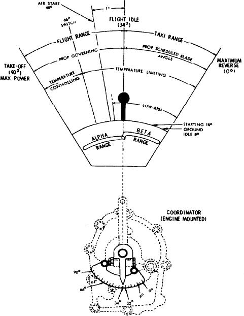
range (alpha) and ground handling range (beta).
The power lever controls power delivered by
For airborne operation, the propeller blade
the engine. There are six positions marked on the
angle and fuel flow for any given power lever
power lever quadrant. See figure 8-7. Listed below
setting are governed automatically according to
Figure 8-7.-Coordinator quadrant markings.
8-7