
the burners in the quantity and at the pressures
required. A secondary function is to supply
compressor bleed air for various purposes in
the engine and aircraft. The compressor provides
space for mounting accessories and engine
parts.
There are two basic types of compressors. The
compressor type is also the engine type, so a
centrifugal-flow compressor is in a centrifugal
engine. Centrifugal-flow compressors have a
compression ratio of 5:1. Present-day axial-
flow compressors have compression ratios
approaching 15:1 and airflows up to 350 lb.
The addition of a fan raises these values to 25:1
and 1,000 lb/sec.
Centrifugal-Flow Compressors
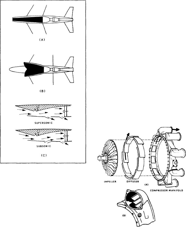
The single entry centrifugal-flow compressor
(fig. 1-15) consists of an impeller (rotor element),
a diffuser (stator element), and a manifold. The
impeller picks up and accelerates air outward to
the diffuser. The diffuser directs air into the
manifold. The manifold distributes air into the
combustion section. Double entry centrifugal-flow
Figure 1-14.-Air entrance designs. (A) Single entrance;
(B) dual entrance; (C) variable entrance.
is to vary the area, or geometry, of the intake
duct. Navy aircraft use this method, incorporating
movable ramps as shown in figure 1-14, view C,
to change the area and shape of the intake
duct.
COMPRESSOR SECTION
The primary function of the compressor
is to supply air in enough quantity to satisfy
the requirements of the combustion burners.
Figure 1-15.-(A) Elements of the centrifugal compressor;
Specifically, the compressor increases the air mass
(B) air outlet elbow with turning vanes for reducing air
pressure losses.
received from the air inlet duct and directs it to
1-13