
There are five basic ways manufacturers
can correct this front-end, low-speed, high-
temperature stall:
1. Lowering the angle of attack on the front
stages so the high angles at low engine speed are
not stall angles
2. Installing a bleed valve in the middle or rear
of the compressor to bleed air and increase airflow
in the front of the compressor at low engine speeds
3. Splitting the compressor into two rotors
and designing the front rotor rpm to decrease
more than the rear rotor at low speeds, so low
front-rotor speed will equal the low choked
airflow
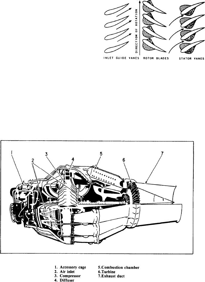
Figure 1-18.-The cascade effect.
4. Installing variable inlet-guide vanes and
variable stators in the front of the first series of
compressor stages so the angle of attack is
The stator has rows of blades or vanes
changed at low engine speed
dovetailed into split rings and attached inside an
5. Using a variable-area exhaust nozzle to
enclosing case. The stator vanes project radially
unload the compressor during acceleration
toward the rotor axis and fit closely on either side
of each stage of the rotor.
NOTE: A combination of any of the above
The compressor case, into which the stator
may be used.
vanes fit, is horizontally divided into halves.
Figure 1-17.-Centrifugal-flow engine (J33).
1-15