
cascade effect is of prime importance in determin-
compressors (fig. 1-16) handles the same airflow
ing blade design and placement.
with a smaller diameter. Small multi-stage
centrifugal-flow engines used in aircraft (fig. 1-17)
The axial-flow compressor has its disadvan-
or as APUs take advantage of these features.
tages, the most important of which is the stall
problem. If, for some reason, the angle of
attack--the angle at which the airflow strikes the
Axial-Flow Compressors
rotor blades--becomes too low, the pressure
zones, shown in figure 1-18, will be of low value,
The term axial flow applies to the axial
and the airflow and compression will be low. If
(straight-line) flow of air through the compressor
the angle of attack is high, the pressure zones will
section of the engine. The axial-flow compressor
be high, and airflow and compression ratio will
has two main elements--a rotor and a stator.
be high.
Each consecutive pair of rotor and stator blades
makes a pressure stage. The rotor is a shaft with
If the angle of attack is too high, the
blades attached to it. These blades impel air rear-
compressor will stall. The airflow over the upper
ward in the same manner as a propeller, by reason
foil surface will become turbulent and destroy the
of their angle and airfoil contour. The rotor,
pressure zones. This will decrease the compression
turning at high speed, takes in air at the
airflow. The angle of attack will vary with engine
compressor inlet and impels it through a series of
rpm, compressor-inlet temperature, and com-
stages. The action of the rotor increases the
pressor discharge or burner pressure. Any action
compression of the air. At each stage it accelerates
that decreases airflow relative to engine speed will
rearward through several stages. The stator blades
increase the angle of attack and increase the
act as diffusers at each stage, partially converting
tendency to stall. The decrease in airflow may
high velocity to pressure. Maintaining high
result from a too-high compressor-discharge
efficiency requires small changes in the rate of
pressure.
diffusion at each stage. The number of stages
During ground operation of the engine, the
depends on the amount of air and total pressure
prime action that causes a stall is choking. If there
rise required. The greater the number of stages,
is a decrease in the engine speed, the compression
the higher the compression ratio. Most present-
ratio will decrease with the lower rotor velocities.
day engines use from 10 to 16 stages.
With a decrease in compression, the volume of
An axial-flow compressor follows the same
air in the rear of the compressor will be greater.
rules and limitations of an aircraft wing. The
This excess volume of air causes a choking action
concept is more complicated than a single airfoil,
in the rear of the compressor with a decrease in
because the blades are close together. Each trailing
airflow. This, in turn, decreases the air velocity
edge blade affects the next leading edge. This
in the front of the compressor and increases the
tendency to stall. If no corrective action is taken,
the front of the compressor will stall at low engine
speeds.
Another reason for engine stall is high com-
pressor inlet air temperatures. High-speed aircraft
may experience an inlet air temperature of 250F
because of ram effect. These high temperatures
cause low compression ratios (due to air density
changes) and will also cause choking in the rear
of the compressor. This choking-stall condition
is the same as the stall condition caused by low
compression ratios due to low engine speeds.
Each stage of a compressor should develop the
same pressure ratio as all other stages. When the
engine slows down or the compressor inlet air
temperature climbs, the front stages supply too
much air for the rear stages to handle, and the
rear stages will choke.
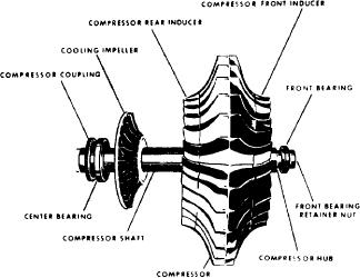
Figure 1-16.-Impeller with inducer vanes as separate pieces.
1-14