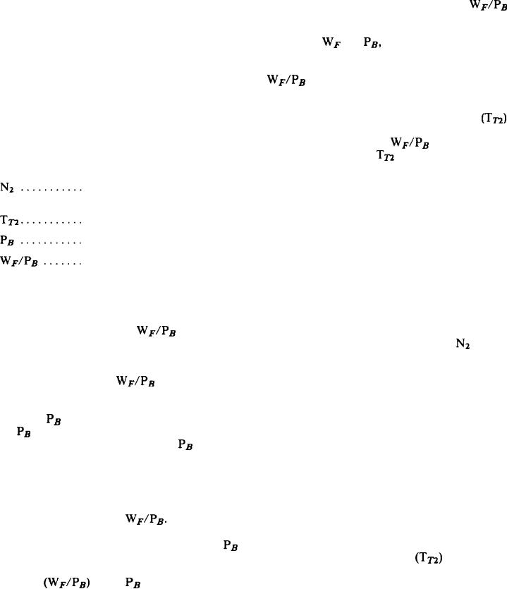
of the OFF position, the high-pressure signal is
equilibrium of this lever. This changes the
replaced by pump interstage pressure. Then
position of a flapper-type servo valve, which is
metered fuel pressure is increased sufficiently to
supplied with regulated high-pressure fuel through
a fried bleed orifice. The resulting change in servo
overcome the spring force, the valve opens, and
fuel flows to the engine. Thereafter, the valve will
pressure between the two orifices is controlled by
provide a minimum operating pressure within the
the position of a piston attached to the throttle
fuel control. This ensures that adequate pressure
valve plunger. T h e motion of this piston
is always available for operation of the servos and
compresses or relaxes a spring that will return the
valves at minimum flow conditions.
multiplying lever to its equilibrium position. An
The power-lever-operated sequencing valve
adjustable minimum-ratio stop on the
also incorporates a windmill bypass feature, which
signal controls engine deceleration. This arrange-
functions when the shutoff valve is closed. This
ment provides a linear relationship between
feature bleeds throttle valve discharge flow to the
and
which results in blowout-
decreasing
free decelerations.
fuel pump interstage to increase the throttle valve
pressure drop and opens the pressure-regulating
An adjustable maximum-ratio stop on the
valve. Damage to the fuel pump from excessive
signal controls engine acceleration. This
pressure is thus prevented during engine wind-
stop is positioned by an acceleration-limiting cam.
It is rotated by a speed-sensing servo system and
milling. The sequencing valve functions in both
translated by a compressor inlet temperature
the normal and manual operating systems.
sensing servo system. The cam is so contoured as
The following designators are used in the
description of the computing system of the
versus engine
to define a schedule of
JFC 25-3 fuel control. These designators should
speed for each value of
that will permit engine
accelerations. This avoids engine overtemperature
be referred to during study of the fuel control.
and surge limits without compromising engine
High-pressure compressor rotor
acceleration time.
speed (RPM)
A burner pressure limiter incorporated in the
fuel control senses burner pressure with respect
Compressor inlet temperature
to ambient pressure. When this differential
Burner can pressure
exceeds a preset maximum, the pressure signal to
the burner pressure motor bellows. This reduces
Ratio of metered fuel flow
bleeding through the limiter valve to ambient
to burner can pressure
pressure. This causes a limitation on fuel flow,
which prevents burner pressure from exceeding
The computing system positions the throttle
a maximum, safe value.
valve to control steady-state engine speed,
A flyweight-type, engine-driven, speed-sensing
acceleration, and deceleration. This is accom-
(the ratio of
plished by using the ratio
governor controls movement of the speed servo
piston through a pilot valve. When
speed
metered fuel flow to engine burner pressure) as
changes, the flyweight force varies and the pilot
a control parameter. Throttle valve positioning
valve is positioned to meter either low- or
of this parameter is achieved through a multiply-
high-pressure fuel to the speed servo piston. The
ing system whereby the
signal is used for
acceleration or deceleration. The steady-state
motion of the piston repositions the pilot valve
speed control is multiplied by a signal propor-
until the speed-sensing system returns to
to provide the required fuel flow.
tional to
equilibrium. The piston incorporates a rack that
meshes with a gear segment on the three-
is sensed in the following manner: A motor
dimensional acceleration cam to provide the speed
bellows is internally exposed to
and the
resulting force is increased by the force of an
signal for acceleration limiting. This piston
position is also used to indicate actual engine
evacuated bellows of equal size. It is directly
speed, and it is connected by a droop lever to a
connected to the motor bellows. The net force,
droop cam.
absolute burner pressure, is transmitted through
The temperature-sensing bellows and servo
a lever system to a set of rollers having a
These rollers
assembly are connected through a lever and yoke
position proportional to
ride between the bellows-actuated lever and a
assembly to the acceleration-limiting cam. The
multiplying lever. The force proportional to
position of this servo piston is indicative of
and is used
compressor inlet temperature
is thus transmitted through the rollers to the
to translate the acceleration cam. It integrates the
multiplying lever. Any change in the roller
temperature and speed signals. The position of
or the
signals upsets the
position
4-22

