
WARNING
The insulation tester operates on high
voltages that are dangerous. Always
discharge the ground circuits before you
touch them. Always connect the ground
lead to a good earth ground before you
turn the tester on. When testing a lead,
connect the tester to the lead before you
turn the test voltage switch on. Be safe.
Operate the equipment and secure the leads
with one hand only.
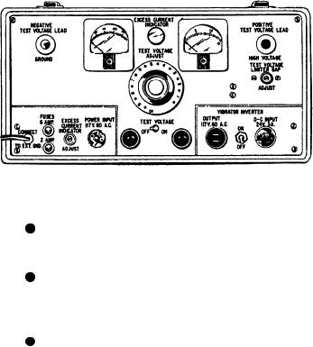
Figure 9-13.--High-voltage insulation tester.
JETCAL ANALYZER AND JET
CALIBRATION TEST UNITS
A voltage control, which controls the
amount of high voltage applied to the test circuit.
Two of the most important factors affecting
turbine engine life are engine speed (rpm) and
A step-up transformer, which steps up the
engine exhaust gas temperature (EGT). Excess
low voltage from the vibrator invertor or 110-volt
exhaust gas temperatures of a few degrees reduce
source to high voltage.
turbine blade life up to 50 percent. Low exhaust
gas temperatures reduce engine efficiency and
A rectifier that changes ac to dc. The test
thrust. Excess engine speed can cause premature
leads are connected to the rectifier dc output side.
engine failure.
A jet calibration test unit tests tailpipe
To calibrate the high-voltage tester, follow
temperatures, engine speed, and other engine
these four steps:
parameters more accurately than the cockpit
gauges. Errors in reading cockpit instruments are
1. Set the microampere and kilovolt meters
made due to the position or height of the seat or
to indicate ZERO when the machine is OFF.
the angle of viewing the gauge. In addition to
2. With the current ON, connect the test
more accurate readings, the new jet test units
leads.
provide a printed readout of engine conditions for
3. Move the voltage control until the needle
trend analysis.
is about one-sixteenth inch past 10, 000 volts. Then
set the test voltage limiter gap. If it is properly
adjusted, the neon light will not flash at the test
BORESCOPE INSPECTION
voltage setting.
4. Adjust the excess current indicator to flash
You will find borescope inspection require-
on and off continually when the microampere
ments listed in the periodic maintenance inspec-
meter shows an excess of 100 microampere
tion cards (PMIC) for scheduled or conditional
leakage.
inspections. Borescopes provide illumination of
internal areas of aircraft engines or engine parts.
When operating the high-voltage tester, be
This illumination allows for internal inspections
sure to make a continuity test with an ohmmeter
that require minimum disassembly, such as the
before you apply the high-voltage insulation test.
removal of port covers or thermocouples.
To hookup the high-voltage tester, follow these
steps:
Types of Borescopes
1. Ground the high-voltage insulation tester
to a good local ground with the grounding lead.
The rigid borescope assembly allows for in-
2. Connect the red high-voltage test lead to
spection of internal engine conditions having a
the high-voltage side of the part to be tested.
direct access. Another type of borescope has a
flexible probe and is commonly known as a fiber-
3. Connect the black ground test lead to the
optic borescope, or fiberscope. The fiber-optic
ground side of the part to be tested.
9-17