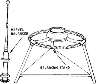
kit 7A100, or its equivalent. See figure 8-22.
its cotter pin) in place at its normal locking
Before performing actual propeller assembly
position.
buildup and balancing, you must always refer to
Final Balance Check
the appropriate technical publication.
Preliminary and final balance has already been
completed on new and overhauled propellers
The final balance check is obtained by adding
before they are disassembled and shipped to an
bolts, washers, and nuts to balancing holes in the
AIMD. Do not perform preliminary balance if
deicer contact ring holder assembly near the outer
edge. If possible, bolts, washers, and nuts should
final balance can be obtained first.
be divided equally on each side of the deicer
NOTE: The final balance check can be
contact ring holder assembly. Do not disturb
erroneous because of residual hydraulic
similar bolts, washers, and nuts, which are painted
red and already located in the balancing holes.
fluid in the propeller dome assembly. You
must make sure the dome assembly is com-
They are used for balance of the holder assembly
pletely drained of any residual hydraulic
itself, not the propeller. Use special bolts, washers,
fluid before installing the dome assembly
and nuts on the deicer contact ring holder
for the final balance cheek.
assembly installed on the propeller. For the
plastic molded holder assembly, use no more
You must obtain horizontal balancing on all
than six AN960-10 washers on one bolt; use no
more than six NAS514P1032-16 bolts and six
propellers during assembly. Horizontal balancing
must be performed in a room free of air currents
MS20364-1032A nuts.
and with the propeller assembly clean and dry.
Obtain final balance with the propeller
The plane of the blades must be horizontal, and
assembly mounted on the horizontal balance
machine, with the plane of the blades horizontal
the blade pitch must be set at 45 degrees.
Do not install the dome cap, low pitch stop
and the dome assembly installed. The sensitivity
of the balance machine must be calibrated so that
assembly, pitchlock regulator assembly, propeller
hub nut, hub mounting bulkhead assembly, and
any unbalance shown by the machine may be
corrected or reversed by applying a restraining
their associated parts. These units are not included
moment of 6 inch-ounces.
as part of the balancing procedure. Install the
If final balance cannot be obtained because
dome assembly without the dome-to-barrel
preformed packing and gear preload shims.
of the maximum limit on the number of bolts,
washers, and nuts that can be added to the deicer
Tighten the dome retaining nut snugly past its
normal locking position. Use masking tape to hold
contact ring holder assembly, it is necessary to
obtain preliminary balance first, and then final
the dome retaining nut special head screw (without
balance. Remove the final balance bolts, washers,
and nuts from the holder assembly, if they are
installed.
CAUTION
The bolts, washers, and nuts that are
colored red must not be removed. These
are used for balance of the holder assembly
itself, not the propeller.
Preliminary Balance
If final balance cannot be obtained, pre-
liminary balance must be obtained by installing
balance washers on the blade balancing plugs of
the light blades.
With the propeller suspended on the balancing
stand, you should place the balance washers on
the shanks of the light blades next to the outboard
Figure 8-22.-Propeller balancing kit (7A100).
8-24

