T h e C O2 s t o r a g e tank is designed for
electrically operated starter motor or a com-
maximum working pressure and is equipped with
pressed, air-operated, air turbine starter motor.
a complete Freon (F-12) refrigeration system,
The electric starter motor requires a source of dc
which is automatically controlled by an internally
voltage. The air turbine motor requires a source
mounted pressure switch. The refrigeration system
of compressed air.
maintains a nominal storage tank pressure. The
CO2 System
storage tank is protected by a safety assembly
consisting of a dual switching valve, which, when
The CO2 fire system for the test facility
in the normal position, places in service one
consists of a 2-ton CO2 storage tank, which
auxiliary automatic refrigeration valve, one safety
incorporates a refrigeration system to maintain
valve, and one high-pressure relief disc. The safety
the liquid carbon dioxide at the proper storage
devices provide complete protection against
pressure; a handwheel-operated shutoff valve on
abnormally high tank pressures. An abnormally
the dip tube of the storage tank; pressure-operated
high pressure usually results from power or
control valves for quickly releasing the carbon
compressor failure continuing over a period of
dioxide; a piping system terminating in the CO2
several hours.
discharge nozzles, strategically located in the
protected areas; and various controls, relays,
PORTABLE UNIVERSAL ENGINE
thermostats, alarm gongs, spurt and flood push
RUNUP TEST SYSTEMS
buttons, and pressure-operated switches. For
complete fire control coverage, the CO2 system
There are several different models of universal
is electrically linked to the interlock system and
test cells in use. Figures 10-20, 10-21, 10-22, and
pressure linked to the main fuel line valve of the
10-23 show some of the more commonly used test
engine fuel supply.
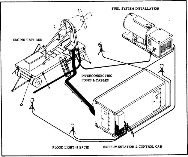
Figure 10-21.-Turboprop engine test system.
10-25

