variable IGVs and variable stators. These systems
Combination Inlet Guide Vane
are the fan variable geometry (FVG) system and
and Bleed Valve System
the compressor variable geometry (CVG) system.
The TF41 engine is a good example of a system
Compressor IGV and stator angle are changed by
that uses fuel as a hydraulic fluid. Fuel pressure
setting the CVG pilot valve to direct fuel pressure
hydraulically operates the inlet guide vanes (IGVs)
to two CVG actuators. A torque motor in the
and the bleed valve ring. The vane control and
single FVG actuator sets the CVG pilot valve.
the bleed-air system prevent compressor surges
See figure 6-3.
during low rpm range operation. The system uses
engine fuel pressure as control and hydraulic force
to vary the angle of the high-pressure compressor
Variable-Area Exhaust Nozzles
variable IGVs. Fuel pressure is used to operate
the high-pressure compressor bleed air valve. See
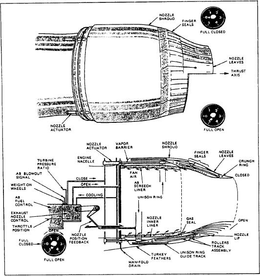
The convergent-divergent geometry of the
figure 6-2. This action decreases the airflow
variable-area exhaust nozzle provides the optimum
through the rear stages of the compressor.
exhaust throat area. The action of the variable-
Compressor surge and choking caused by in-
area nozzle is achieved by close tolerance over-
creased air velocity is prevented.
lapping seals, which bridge adjacent leaf segments
to provide a relatively smooth surface contour.
Variable Inlet Guide Vanes and Stators
The TF30-P-414/414A installed in the F-14 air-
craft uses the hydraulic action of fuel to position
The F404-GE-400, installed in the F/A-18 air-
the nozzles. See figure 6-4.
craft, uses two different systems to operate the
Figure 6-4.-Variable area exhaust nozzle actuation.
6-5

