
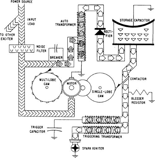
Figure 6-6 is a functional schematic of the
a voltage in the secondary windings. This voltage
system. You should refer to this figure when
causes a pulse of current to flow into the storage
studying the theory of operation of a capacitor-
capacitor through a rectifier. This rectifier limits
discharge system. This schematic shows a cam-
the flow to a single direction. With repeated
operated breaker point. Most modern systems
pulses, the storage capacitor thus assumes a
have had all mechanical parts replaced with
charge, up to a maximum of approximately 4
electronic solid-state devices. System operation is
joules. One joule per second equals 1 watt of
discussed in the following paragraphs.
power.
A 24-volt dc input voltage is sent to the input
The storage capacitor connects to the spark
receptacle of the exciter. The voltage first goes
igniter through the triggering transformer and
through a noise filter. This filter blocks conducted
through a normally open contactor. When the
noise voltage from feeding back into the aircraft
charge on the capacitor has built up, the contactor
electrical system. This input voltage operates a dc
closes by the mechanical action of the single-lobe
motor, which drives one 16-lobe and one 1-lobe
cam. A portion of the charge flows through the
cam. The input voltage is also sent to two breakers
primary of the triggering transformer and the
actuated by the 16-lobe cam.
capacitor connected in series with it.
From the breakers, a rapidly interrupted
This current induces a high voltage in the
current is sent to the autotransformer. When the
secondary, which ionizes the gap at the spark
breaker closes, the flow of current through the
igniter. Thus, when the spark igniter conducts,
primary winding of the transformer generates a
the storage capacitor discharges the remainder of
magnetic field. When the breaker opens, the flow
its accumulated energy through it. Energy also
of current stops. The collapse of the field induces
comes from the charge from the capacitor that
Figure 6-6.-Functional schematic diagram of a capacitor discharge ignition system.
6-8