relay vital information concerning safety of flight.
Whenever practical, assembly design allows bulb
replacement in flight without the use of tools.
Most warning light designs have a push-to-test
feature or a test switch that lets you determine
if the bulb is good. The test switch energizes
various test relays, which, in turn, either provide
power or a ground circuit for energizing the lights.
This allows you to check the bulb without
operating the equipment.
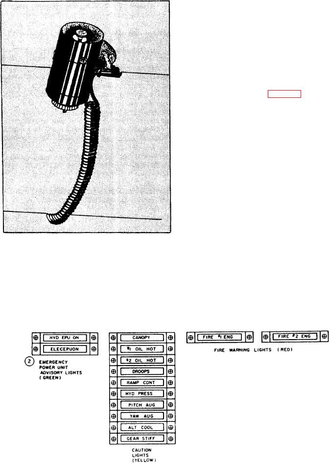
Legend-type lights (fig. 4-11) show specific
functions on the lens surface. They are prominent
on late model aircraft.
The warning lights are red. They warn the
crew of an emergency or unsafe operat-
ing condition, which requires immediate
corrective action.
The caution lights are yellow. They alert
the crew to a minor malfunction or im-
pending dangerous condition requiring attention,
but not necessarily immediate corrective action.
The advisory lights are green. They show
the crew a safe or normal configuration,
or a performance condition.
Figure 4-10.-Cockpit utility light.
Indicator lights must be bright enough to see
during daylight operation but not bright enough
to cause eyestrain at night. You obtain brilliance
The construction of indicator lights varies,
control by connecting resistors in the lighting
depending upon the particular job they perform.
circuit, and by placing dimmer caps on the lights.
Other ways of control are special adaption of edge
They mount in the aircraft where they are easily
noticeable when glowing. It is important that bulb
lighting, and special types of lenses that dim by
replacement be quick and easy since some lights
twisting the lens.
Figure 4-11.-Legend-type lights.
4-11

