
The airspeed indicator is a differential pressure
shows a cutaway view of a typical airspeed
instrument. It measures the difference between the
indicator.
pressures in the impact pressure line and in the
An airspeed indicator has a cylindrical, airtight
static pressure line. The two pressures are equal
case that connects to the static line from the
when the aircraft is stationary on the ground.
pitot-static tube. Inside the case is a small aneroid
Movement through the air causes pressure in the
diaphragm of phosphor bronze or beryllium
impact line to become greater than that in the
copper. The diaphragm is very sensitive to
static line. This pressure increase causes the
changes in pressure, and it connects to the
diaphragm to expand. The expansion or con-
impact pressure (pitot) line. This allows air from
traction of the diaphragm goes through a series
the pitot tube to enter the diaphragm. The side
of the diaphragm fastens to the case and is rigid.
to regulate needle position. The needle shows the
The needle or pointer connects through a series
pressure differential in MPH or knots. (All speeds
and distances are in nautical miles.)
diaphragm.
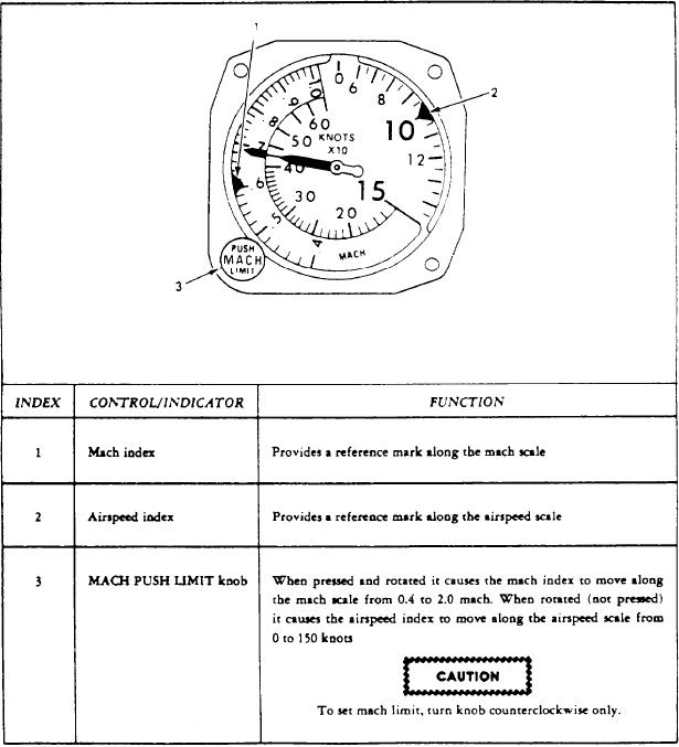
Figure 6-5.-Airspeed/Mach indicator.
6-4