
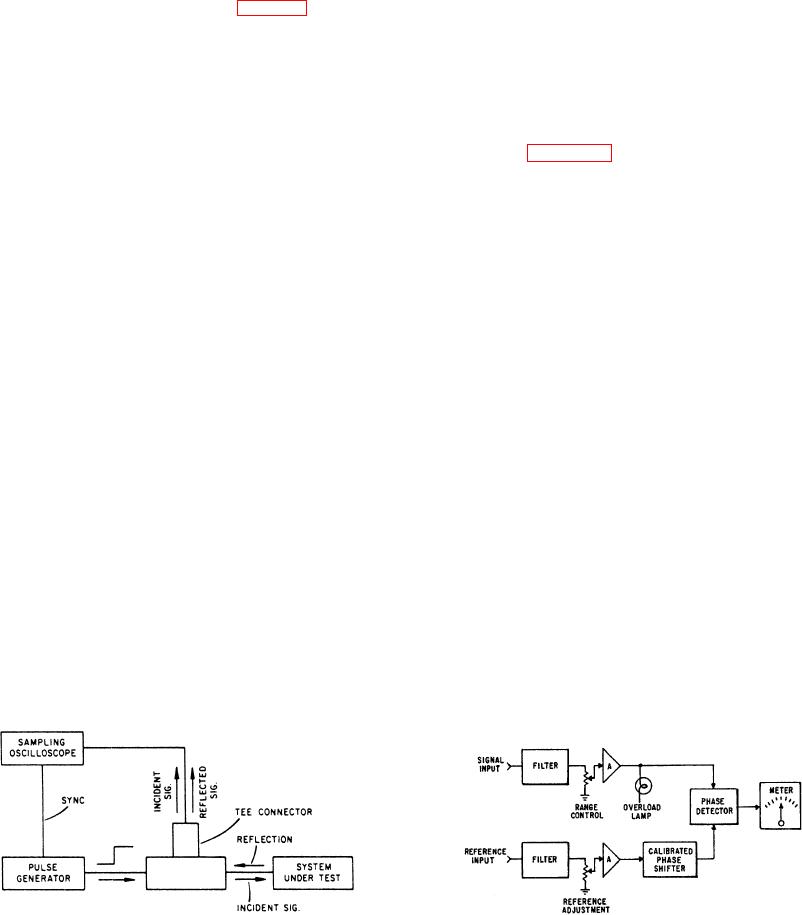
the newer, specialized reflectometers (fig. 2-7). The pulse
presents problems. In most applications, interest lies in
generator develops a fast (or incident) step. This step then
the phase relationship of the basic frequencies, regardless
passes through a TEE connector and goes into the system
of any harmonics that are present. One requirement of a
under test. The sampling oscilloscope is also attached to
phase measuring device is measuring the phase difference
the TEE connector, and the incident step, along with the
between two discrete frequencies. It must accomplish this,
reflected waveform, shows on the CRT. Analysis of the
regardless of phase and amplitude of other components of
the waveform.
shows the type of impedance variation in the system
The basic block diagram of a phase angle voltmeter is
under test.
shown in figure 2-8. You should refer to it while reading
When the fast-rise input pulse meets with a
this section. There are two inputs--the signal and the
discontinuity or an impedance mismatch, the resultant
reference. Both channels contain filters that pass only the
reflections appearing at the feedpoint are compared in
fundamental
Harmonics
are
highly
phase, time, and amplitude with the original pulse. Also,
attenuated. Each channel has a variable amplitude
since distance relates to time and the amplitude of the
control and amplifiers to increase the variety of signals
reflected step directly relates to impedance, the
you can check.
comparison shows the distance to the fault, as well as an
By placing a calibrated phase shifter into the
indication of its nature. Time-domain reflectometry shows
reference channel, that channel signal can be phase
both the position and the nature (resistive, inductive, or
shifted to correspond to the other channel. The phase
capacitive) of each line discontinuity. It also reveals the
detector will detect this action and it will also show on the
characteristic impedance of the line and shows whether
meter.
losses are parallel or series losses.
The calibrated phase shifter connects to a switch
(whose position corresponds to the 0-degree, 90-degree,
180-degree, and 270-degree phase shift) and a
PHASE ANGLE VOLTMETER
potentiometer (whose dial is calibrated from 0 degree to
90 degrees). The total phase shift is the sum of the two
You can determine the overall accuracy of many
readings.
electronic parts by measuring phase angles in computing
The phase detector is a balanced diode bridge-type
transformers, computing amplifiers, and resolver systems.
demodulator. Its output is proportional to the signal
In the past, the most common method used for measuring
amplitude times the cosine of the angle of phase
phase shift or phase angles between signals was
difference between the signal input and the reference
observing patterns on an oscilloscope. With this method,
input.
it was hard to determine small angles and difficult to
If the reference input is phase shifted until it is in
translate various points into angles and sines of angles.
phase or 180 degrees out of phase with the signal input,
When one of the signals contained harmonic distortion or
the output from the phase detector is proportional to the
noise, this interference limits the use of oscilloscope
signal input amplitude (the cosine of the angle is unity). If
patterns.
the reference input is phase shifted until it is 90 degrees
In any complex waveform containing a basic
out of phase
frequency and harmonics, measuring phase shifts
Figure 2-7.-Typical time domain reflectometer.
Figure 2-8.-Phase angle voltmeter, block diagram.