! Aluminum trailing edge cap
! Aluminum or polyurethane and nickel abrasion
leading edge strip
Additionally, rotary rudder blades may have
deicing provisions, such as electrothermal blankets that
are bonded into the blade's leading edge. or a neoprene
anti-icing guard embedded with electrical heating
elements.
Q4-17.
What is the main advantage of rotary-wing
aircraft over fixed-wing aircraft?
Q4-18.
What are the three types of landing gear used
on helicopters?
Q4-19.
The directional control and antitorque action
of the helicopter is provided by what group?
AIRCRAFT HYDRAULIC SYSTEMS
LEARNING OBJECTIVE:
Identify the
components of aircraft hydraulic systems and
recognize their functions.
The aircraft hydraulic systems found on most naval
aircraft perform many functions. Some systems
operated by hydraulics are flight controls, landing gear,
speed brakes, fixed-wing and rotary-wing folding
mechanisms, auxiliary systems, and wheel brakes.
Hydraulics has many advantages as a power source
for operating these units on aircraft.
! Hydraulics combine the advantages of
lightweight, ease of installation, simplification
of inspection, and minimum maintenance
requirements.
! Hydraulics operation is almost 100-percent
efficient, with only a negligible loss due to
fluid friction.
However, there are some disadvantages to using
hydraulics.
! The possibility of leakage, both internal and
external, may cause the complete system to
become inoperative.
! Contamination by foreign matter in the system
can cause malfunction of any unit. Cleanliness
in hydraulics cannot be overemphasized.
COMPONENTS OF A BASIC SYSTEM
Basically, any hydraulic system contains the
following units:
! A reservoir to hold a supply of hydraulic fluid
! A pump to provide a flow of fluid
! Tubing to transmit the fluid
! A selector valve to direct the flow of fluid
! An actuating unit to convert the fluid pressure
into useful work
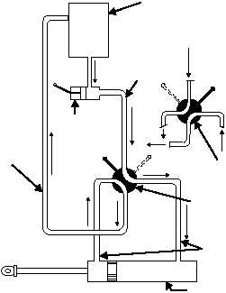
A simple system using these essential units is
shown in figure 4-21.
You can trace the flow of fluid from the reservoir
through the pump to the selector valve. In figure 4-21,
the flow of fluid created by the pump flows through the
valve to the right end of the actuating cylinder. Fluid
pressure forces the piston to the left. At the same time,
the fluid that is on the left of the piston is forced out. It
goes up through the selector valve and back to the
reservoir through the return line.
When the selector valve is moved to the position
indicated by the dotted lines, the fluid from the pump
flows to the left side of the actuating cylinder.
Movement of the piston can be stopped at any time
simply by moving the selector valve to neutral. When
the selector valve is in this position, all four ports are
closed, and pressure is trapped in both working lines.
4-19
ANF0421
PRESSURE
LINE
SELECTOR VALVE
IN "DOWN"
POSITION
RETURN
LINE
SELECTOR VALVE
IN "UP"
POSITION
WORKING
LINES
HAND
PUMP
ACTUATING
UNIT
RESERVOIR
Figure 4-21.—Basic hydraulic system, hand pump operated.