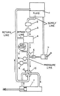
Figure 4-22 shows a basic system with the addition
of
a
power-driven
pump
and
other
essential
components. These components are the filter, pressure
regulator, accumulator, pressure gauge, relief valve,
and
two
check
valves.
The
function
of
these
components is described below.
The filter (fig. 4-22) removes foreign particles
from the fluid, preventing moisture, dust, grit, and other
undesirable matter from entering the system.
The pressure regulator (fig. 4-22) unloads or
relieves the power-driven pump when the desired
pressure in the system is reached. Therefore, it is often
referred to as an unloading valve. With none of the
actuating units operating, the pressure in the line
between the pump and selector valve builds up to the
desired point. A valve in the pressure regulator
automatically opens and fluid is bypassed back to the
reservoir. (The bypass line is shown in figure 4-22,
leading from the pressure regulator to the return line.)
NOTE:
Many aircraft hydraulic systems do not
use a pressure regulator. These systems use a pump that
automatically adjusts to supply the proper volume of
fluid as needed.
The accumulator serves a twofold purpose.
1.
It serves as a cushion or shock absorber by
maintaining an even pressure in the system.
2.
It stores enough fluid under pressure to provide
for emergency operation of certain actuating
units.
The accumulator is designed with a compressed-air
chamber separated from the fluid by a flexible
diaphragm, or a removable piston.
The
pressure gauge
indicates the amount of
pressure in the system.
The relief valve is a safety valve installed in the
system. When fluid is bypassed through the valve to the
return line, it returns to the reservoir. This action
prevents excessive pressure in the system.
Check valves
allow the flow of fluid in one
direction only. There are numerous check valves
installed at various points in the lines of all aircraft
hydraulic systems. A careful study of figure 4-22 shows
why the two check valves are necessary in this system.
One check valve prevents power pump pressure from
entering the hand-pump line. The other valve prevents
hand-pump pressure from being directed to the
accumulator.
HYDRAULIC CONTAMINATION
Hydraulic contamination is defined as
foreign
material in the hydraulic system of an aircraft. Foreign
material might be grit, sand, dirt, dust, rust, water, or
any other substance that is not soluble in the hydraulic
fluid.
There are two basic ways to contaminate a
hydraulic system. One is to inject particles, and the
other is to intermix fluids, including water.
Particle contamination in a system may be
self-generated
through
normal
wear
of
system
components. It is the injection of contaminants from
outside that usually causes the most trouble. Regardless
of its origin, any form of contamination in the hydraulic
system will slow performance. In extreme cases, it
seriously affects safety.
A single grain of sand or grit can cause internal
failure of a hydraulic component. Usually, this type of
contamination
comes
from
poor
servicing
and
fluid-handling procedures. For this reason, the highest
4-20
ANf0422
1. Reservoir
2. Power pump
3. Filter
4. Pressure regulator
5. Accumulator
6. Check valves
7. Hand pump
8. Pressure gauge
9. Relief valve
10. Selector valve
11. Actuating unit
Figure 4-22.—Basic hydraulic system with addition of power
pump.