and it provides the means to accurately check out the
operating characteristics of the hydraulic system and
components at pressures up to 4,500 psi. This can be
accomplished without running the aircraft engine.
The power unit is used at the organizational level for
all aircraft where requirements for hydraulic fluid
flow are not significant.
The power unit consists of an electrically
powered, pump impelled, hydraulic system housed in
an aluminum frame structure and mounted on casters.
The structure is mounted on two swivels and two
fixed casters, and is equipped with a manual tow bar
for ease of mobility. It also has a hand-operated brake
to prevent unintended movement of the power supply.
The control panel is mounted on one end of the
power unit. Other controls and components are
accessible through removable side panels. The power
unit is equipped with an electrical cable and hydraulic
hoses that are stored on a rack attached to one end of
the unit when they are not in use. The power unit
consists of two basic systems: a hydraulic system and
an electrical system.
Hydraulic and electrical
schematics are provided on etched plates permanently
attached to the unit.
For a more detailed description of this power unit
and its operating procedures, refer to the NAVAIR
17-15BF-76.
A/M27T-5 Portable Hydraulic Power Supply
The A/M27T-5 portable hydraulic power supply
(fig. 4-11), made by Janke and Company, Inc., is
replacing the AHT-64 hydraulic test stand made by
Teledyne Sprague Engineering. The A/M27T-5 is a
modified AHT-64 portable, table hydraulic power
supply unit. It is a self-contained, diesel powered,
trailer-mounted unit capable of providing a source of
hydraulic fluid at controlled pressures and flow rates
from 0 gpm at 0 psi to 24 gpm at 3,000 psi, or 13 gpm
at 5,000 psi under ambient temperatures of –25°F to
+115°F and relative humidity of 95 percent. The
Model 3-53 Detroit diesel engine is used in the
A/M27T-5. Minor changes were made to the physical
location of system components to make maintenance
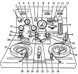
easier. See figure 4-12 for a view of the A/M27T-5
central panel. Table 4-5 explains the functions of
each control and indicator on the panel.
AHT-63 Portable Hydraulic Test Stand
The Portable Hydraulic Test Stand AHT-63
(fig. 4-13) is powered by an electric motor. The
motor operates at 50 hp, 3,520 rpm, and is dripproof:
it is capable of operating on 220/440-volt,
three-phase, 60-Hz (cycle) current. The motor is a
double-end shaft type. One end drives the
high-pressure pump, and the other end drives the oil
cooler fan. The motor is equipped with a magnetic
starter, a thermal overload relay for protection, a
reverse phase relay to protect the pump unit from
reverse rotation caused by incorrect electrical power
phasing, and a low-pressure switch to stop the motor
when boost pressure is too low at the high-pressure
pump inlet. It has 50 feet of neoprene-covered,
three-phase electric cable with ground wire, which
operates at either 220 or 440 volts. The control circuit
is further protected by a circuit breaker and fuses.
PRINCIPLES OF OPERATION.— The
AHT-63 and A/M27T-5 operate in basically the same
manner. They differ in their starting and stopping
procedures and the electrical outlet used to furnish
power to the electric motor. Before you use the
AHT-63 test stand, you need to know how it works
and the location and function of all switches, controls,
and instruments. See figure 4-14 and table 4-6. For
specific instructions on its use, refer to the Handbook
of Operation, Service, and Overhaul Instruction, NA
17-15BF-65, and the applicable MIM.
MINIMUM REQUIREMENTS.— Before you
operate the portable hydraulic test stand, follow the
specific instructions for its inspection, turnup, aircraft
Figure 4-12.—A/M27T-5 main control panel controls and
indicators.
4-27