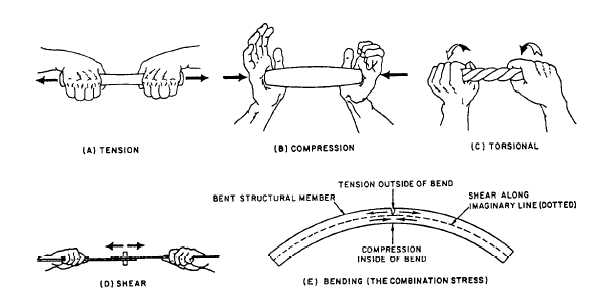
Figure 1-19.—Five stresses acting on an aircraft.
rotary rudder head is driven by the tail gearbox. Change
in blade pitch is accomplished through the pitch change
shaft that moves through the horizontal shaft of the tail
gearbox. As the shaft moves inward toward the tail
gearbox, pitch of the blade is decreased. As the shaft
moves outward from the tail gearbox, pitch of the blade
is increased. The pitch control beam is connected by
links to the forked brackets on the blade sleeves.
A flapping spindle for each blade permits flapping
of the blade to a maximum of 10 degrees in each
direction.
Rotary Rudder Blades
The blades are on the rotary rudder head. Each blade
consists of the following:
• Aluminum spar
• Aluminum pocket with honeycomb core
• Aluminum tip cap
• Aluminum trailing edge cap
• Abrasion strip
In addition, those blades that have deicing pro-
visions have a neoprene anti-icing guard, embedded
with electrical heating elements. The root end of the
blade permits attaching to the rotary rudder head
spindles. The abrasion strip protects the leading edge of
the blade from sand, dust, and adverse weather
conditions. The skin is wrapped completely around the
spar, and the trailing edge cap is installed over the edges
of the skin at the trailing edge of the blade, The tip cap
is riveted to the outboard end of the blade.
STRUCTURAL STRESS
Learning Objective: Identify the five basic
stresses acting on an aircraft.
Primary factors in aircraft structures are strength,
weight, and reliability. These three factors determine the
requirements to be met by any material used in airframe
construction and repair. Airframes must be strong and
light in weight. An aircraft built so heavy that it could
not support more then a few hundred pounds of
additional weight would be useless. In addition to
having a good strength-to-weight ratio, all materials
must be thoroughly reliable. This reliability minimizes
the possibility of dangerous and unexpected failures.
Numerous forces and structural stresses act on an
aircraft when it is flying and when it is static. When it is
static, gravity force alone produces weight. The weight
is supported by the landing gear. The landing gear also
absorbs the forces imposed during takeoffs and
landings.
During flight, any maneuver that causes
acceleration or deceleration increases the forces and
stresses on the wings and fuselage. These loads are
tension, compression, shear, bending, and torsion
stresses. These stresses are absorbed by each component
of the wing structure and transmitted to the fuselage
structure. The empennage, or tail section, absorbs the
same stresses and also transmits them to the fuselage
structure. The study of such loads is called a “stress
analysis.” The stresses must be analyzed and considered
when an aircraft is designed. These stresses are shown
in figure 1-19.
1-19


