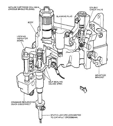
The lower face of the RH ballistic manifold
(fig. 5-16) has four connectors. Two of these
connectors accommodate the RH seat initiation
trombone tube (outboard) and the harness locks
to release the trombone tube (inboard). The
connections are secured by a key-operated, quick-
release pin that passes through a hole in the
manifold and cutouts in the trombone tubes. The
other two connectors accommodate the gas pipe
from the barostatic release unit and the gas pipe
to the lower drogue bridle release mechanisms.
Manifold Assembly Left-Hand.— The left-
hand (LH) assembly is a gas distribution center
that is connected to the seat bucket trombone
tubes and houses a seat rocket initiation system
check valve. The assembly also provides a
mounting for a delay cartridge.
The upper face of the LH ballistic manifold
(fig. 5-17) has three socket connectors, to which
are connected a flexible hose to the LH pitot
deployment mechanism, a rigid pipe from the
RH multipurpose initiator, and a delay initia-
tor.
The lower face of the LH ballistic manifold
has three socket connectors. Two of these
connectors accommodate the LH seat initiation
trombone tube (outboard) and the underseat
rocket motor trombone tube (inboard). The other
connector accommodates a gas pipe to the thermal
batteries. A bracket on the front face of the
manifold accommodates the shoulder harness
control mechanism torque shaft. A connection on
the aft face accepts a gas pipe from the LH
multipurpose initiator.
THERMAL BATTERIES.— Two thermal
batteries (fig. 5-18) supplying power for sequencer
operation are mounted together in a manifold on
the LH main beam.
Seat Bucket Assembly
The seat bucket assembly (fig. 5-19) fits onto
the lower portion of the main beams and
Figure 5-16.-Right-hand ballistic manifold.
5-16