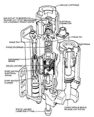
Figure 5-13.-Multipurpose initiator, left-hand.
assembly, a spring-loaded firing pin, and an
impulse cartridge. A gas passage through the unit
body connects the cartridge breech to the lower
end of the start switch plunger. Incorporated into
the unit body, but mechanically separate, is a
lower drogue bridle release unit.
The static lanyard assembly comprises a
lanyard, precoiled into a cylindrical container and
with special fittings swaged on to each end. The
upper end fitting incorporates a wedge-shaped
disconnect device, which engages with the lower
end (similarly wedge-shaped) of a spring-loaded
firing pin positioned below the cartridge. The
lower end fitting protrudes through the lower end
of the body and is retained by a shear pin. When
the seat is installed on a catapult, the protruding
lower end fitting locates in one of the catapult-
mounted ballistic latches.
The start switch assembly is installed vertically
and comprises a series of metal sleeves and
insulated sections to form an electrical switch
assembly. An internal plunger is partially sleeved
with insulating material, has a short gold-plated
section, and incorporates a piston head at its lower
end. Movement of the plunger before operation
is prevented by a shear pin. Two start switch
assemblies are incorporated into the multipurpose
initiators. During ejection, the start switches
supply a start signal to the sequencer at the correct
time in the sequence.
The impulse cartridge is percussion operated
by the firing pin and is screwed into a breech at
the upper end of the body. A gas gallery machined
in the upper part of the cartridge ensures even
distribution of gas pressure when the cartridge
fires.
TIME-DELAY MECHANISM.— The time-
delay mechanism consists of a spring-loaded rack
assembly in mesh with a gear train controlled by
5-13


