harness straps to retract but prevent them from
extending. When in the normal unlocked state,
automatic locks protect the occupant against rapid
forward movement under high g-loading.
PARACHUTE DEPLOYMENT ROCKET
MOTOR MK 122 MOD 0.— The parachute
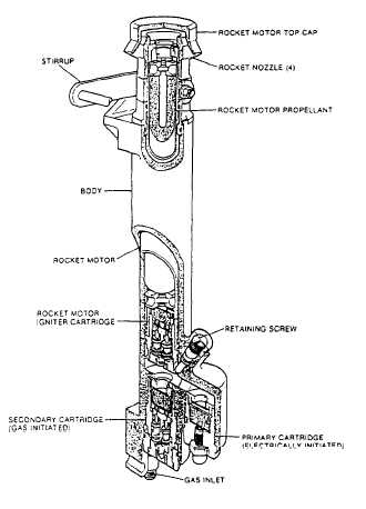
deployment rocket motor (PDRM) (fig. 5-9) is
mounted on the LH main beam of the seat. When
initiated by the sequencer, restraint release unit,
or manual override (MOR) system, the PDRM
extracts the personnel parachute from its stowage
by means of a withdrawal line attached to the
deployment sleeve.
The PDRM is a sealed unit. It consists of a
cylindrical body that contains a gas-operated
secondary cartridge in a breech at the lower end
and a rocket with an integral gas-operated igniter
cartridge in a barrel at the upper end. In a parallel
connected chamber is an electrically initiated
primary cartridge. A gas inlet is connected by a
gas pipe to the harness release system.
Figure 5-9.-Parachute deployment rocket motor (Mk 122
Mod 0).
Fitted around the rocket is a sliding stirrup,
which is connected to the parachute withdrawal
line and is free to slide down the rocket as it leaves
the barrel.
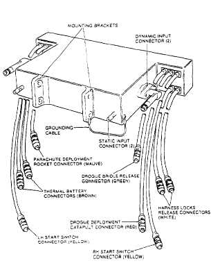
ELECTRONIC SEQUENCER.— The NACES
sequencer assembly (fig. 5-10) is composed of the
sequencer, connectors to the interface with pitot
static and dynamic pressure sources, and cable
loom sleeving. It is mounted across the main beam
assembly, below the parachute assembly. Upon
activation, the sequencer determines the ejection
mode and controls the functions of the drogue
release, parachute deployment, and seat/man
separation.
BAROSTATIC RELEASE UNIT (BRU).—
The barostatic release unit (fig. 5-11) provides a
housing for the cartridge that provides the gas
flow to initiate harness release and parachute
rocket deployment. The cartridge is activated
either electrically by the sequencer or by the right-
hand start switch (via the delay mechanism). The
cartridge incorporates an aneroid capsule to
prevent mechanical initiation above a preset
altitude. The cartridge may also be initiated by
operation of the MOR handle after ejection.
Figure 5-10.-Electronic sequencer.
5-10


