overcoming the springs and retaining the multi-
purpose initiator lanyard spigots (fig. 5-3).
PISTON.— The piston consists of a light alloy
tube, attached to the lower end of which is a
necked end fitted with piston rings to provide a
gas seal between the piston and the barrel. At the
upper end of the piston is a breech, into which
the cartridge-activated initiator is inserted. The
breech has a groove machined around its outer
diameter, into which the plunger of the top latch
mechanism on the seat main beams engages when
the seat is installed on the catapult. A V-groove
in the top of the breech engages a dowel on the
seat top crossbeam when the seat is installed in
the aircraft (fig. 5-3).
CATAPULT MANIFOLD VALVE.— The
catapult manifold valve provides an interface
between the ejection seat and the catapult. The
catapult manifold valve is mounted on the top of
the catapult. The valve is locked onto the
cartridge-activated initiator by a spring-loaded
plunger and a retaining pin. The valve contains
two inlet ports that connect the hoses from the
time delays.
Main Beams Assembly
The main beams assembly is manufactured
almost entirely from light alloy and comprises two
parallel main beams bridged by top and bottom
crossbeams. Bolted to the inside face of each main
beam are three slippers, which engage in the guide
rails on the catapult. Two-seat bucket runner
guides are attached to the front face of each main
beam and accommodate the top and bottom seat
bucket slippers. The slippers provide smooth
movement of the seat bucket and incorporate
threaded studs for attachment of the seat bucket
to the main beams. Friction pads are incorporated
in the studs to damp out lateral movement of the
seat bucket. Drogue bridle retaining channels are
secured to the rear of both main beams. Locating
pins for the parachute container hooked brackets
are bolted to the upper outside face of each main
beam. Interference blocks on the right-hand (RH)
beam (forward seat) or left-hand (LH) beam (aft
seat) correspond with interference devices on the
catapult and the seat bucket to ensure that only
the correct assemblies are installed in forward and
aft cockpits.
TOP CROSSBEAM.— The top crossbeam
accepts and locates the top of the catapult, and
takes the full thrust of the catapult during
ejection. Incorporated into the crossbeam is the
upper drogue bridle release unit. A dowel in the
top crossbeam locates in one of the catapult
breech V-grooves when the seat is installed in the
aircraft.
BOTTOM CROSSBEAM.— The bottom
crossbeam retains and separates the main beams
at the bottom end. Incorporated into the
crossbeam is a gas passage that forms part of the
drogue bridle release system.
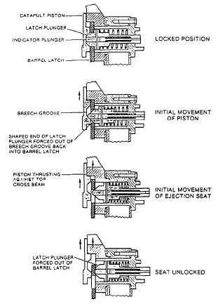
TOP LATCH ASSEMBLY.— The seat
structure is secured to the catapult by the top latch
assembly (fig. 5-6) fitted to the LH main beam.
The assembly consists of a housing that contains
a spring-loaded latch plunger, one end of which
is shaped to engage the catapult piston. The
plunger may be withdrawn by using the top latch
withdrawal tool (handwheel). Passing through the
center of the latch plunger is a spring-loaded
indicator plunger. When the ejection seat is fitted
Figure 5-6.-Operation of top latch assembly.
5-7


