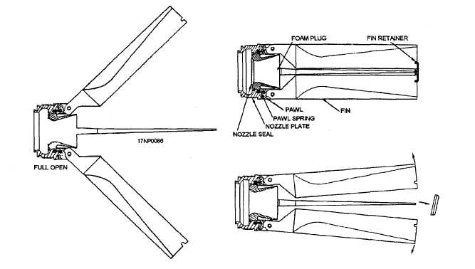
Figure 2-9.—Mk 16 motor, nozzle, and fin assembly.
The nozzle inserts of the Mk 4 motors are standard
or straight cut (fig. 2-8, view A), while the Mk 40 motor
nozzle inserts are scarfed or cut at an angle (fig. 2-8,
view B). The scarfed nozzles used on the Mk 40 motor
impart a stabilizing spin to the rocket when launched at
low initial-launch speeds, such as from helicopters and
low-speed aircraft. A rocket using the Mk 40 motor is
designated a LSFFAR (low-speed, folding-fin, aircraft
rocket) and is used only on helicopters or low-speed
aircraft.
All Mk 16 motors have a single nozzle with four
straight folding fins (fig. 2-9) that attach to the aft end
of the motor tube by threads. To protect the propellant
grain from moisture and to promote propellant grain
ignition, the nozzle opening is closed by a thin metal seal
and a foam plug. A light plastic fin retainer holds the
fins folded within the diameter of the rocket until
propellant ignition. On ignition, the fin retainer is blown
off. Gas pressure exerted on the heels of the fins pushes
the fins open as they emerge from the launcher tube.
The fins are then locked in the flight position by the
spring-loaded pawls.
The Mk 16 Mod motor has a modified igniter and a
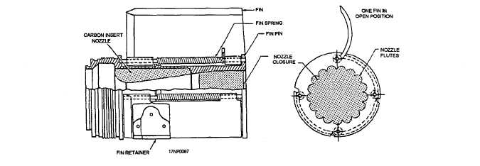
modified nozzle and fin assembly. The nozzle and fin
assembly (fig. 2-10) contains four, spring-loaded,
wraparound fins inside the motor diameter. The steel
nozzle expansion cone has flutes that cause the rocket
to spin during free flight. This permits the rocket to be
launched from high-speed aircraft, helicopters, and
low-speed aircraft.
Figure 2-10.—Mk 71 Mod 0 motor, nozzle, and fin assembly.
2-7


