The barometric switch in the RAWS auto-
matically resets its altitude reference pressure to
ground level before flight. When 700 feet above
takeoff altitude has been reached, the switch actuates
and changes the RAWS reliability circuit. At this
point, the radar altimeter reliability signal is inhibited.
This prevents nuisance warnings when the aircraft is
flying above the operating range of the switch.
AUTOMATIC DIRECTION FINDER (ADF)
The Direction Finder Set, AN/ARN-83, is known
as a low frequency automatic direction finder
(LF/ADF). This system is a radio navigational aid
that operates in the low-to-medium-frequency range.
It continuously indicates the bearing to a selected
radio station, acts as a manual direction finder, and as
a conventional low-frequency radio receiver for voice
and unmodulated transmissions.
The LF/ADF is
sometimes referred to as a radio compass.
Major Components
The AN/ARN-83 direction finder set consists of
four major components. The y are the R-1391/
ARN-83 receiver, the C-6899/ARN-83 control panel,
the AS-1863/ARN-83 loop antenna, and the ADF
sense antenna.
RADIO RECEIVER R-1391/ARN-83.— The
radio receiver is remotely controlled from the ADF
control. It does all processing of signals received by
the loop and sense antennae and sends bearing
information to the navigation indicator group.
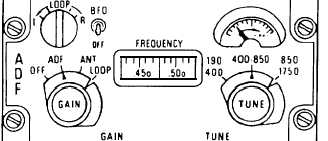
DIRECTION FINDER CONTROL PANEL
C-6899/ARN-83.— The control panel controls all
functions of the system (fig. 2-11). Selection of the
three modes of operation is accomplished here.
Manual control of the loop antenna is done using the
LOOP knob. The tune knob tunes the receiver for the
Figure 2-11-Direction finder control panel C-6889/ARN-83.
station, and it is visually indicated through the
frequency dial.
The tuning meter indicates the
strength of the receiver signal. The BFO switch
causes a tone to be produced for tuning purposes.
LOOP ANTENNA AS-1863/ARN-83.— This
antenna is a flat, one-piece, sealed unit. It consists of
four ferrite-cored coils arranged in a rectangle. Two
coils line up parallel to the fore-aft axis of the aircraft,
and the other two are perpendicular to the axis. Each
pair of coils provides a signal that is sent to the
receiver for processing.
ADF SENSE ANTENNA.— The ADF sense
antenna element is basically an aluminum panel
connected to the input of the lightning arrester. This
panel is encased in fiber glass and mounted flush with
the fuselage. The loop antenna is physically mounted
on the sense antenna.
Functional Description
There are three functional modes with the
LF/ADF. These modes are (1) ADF mode, (2) loop
mode, and (3) antenna mode. The direction finder set
provides audio to the intercommunication system in
all three modes of operation.
ADF MODE.— In the ADF mode, the loop
antenna signals are mixed with the nondirectional
sense antenna signal in the receiver. This signal is
then detected for audio to be sent to the headsets. The
bearing coordinate data is produced by the receiver
error correction servomotor network. This is then
sent to the navigation indicator for display.
LOOP MODE.— In the loop mode, the fixed loop
antenna RF signal is modulated and detected in the
receiver. The resulting audio error signal is used to
produce an audio tone signal that is fed to the
intercommunication system.
The servomotor
net work is then manually controlled to null the audio
tone. At the null, the output of the receiver will
represent relative bearing to the radio station.
ANTENNA MODE.— This mode causes the
system to act just like a normal radio receiver. It
receives a voice or continuous wave (CW) signal at
the sense antenna, which is detected and amplified by
the receiver. The receiver then sends the audio to the
ICS. In this mode of operation, there is no bearing
data signal being developed.
2-12


