Major Components
The AN/ARN-84(V) TACAN set consists of five
major components. They are the control panel,
C-9054/ARN-84(V); the receiver-transmitter,
RT-1022/ARN-84(V); the signal data converter,
CV-2837/ARN-84(V); the RF transmission line
switch, SA-1818/A; and the antenna assembly,
AS-26281A.
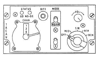
TACAN CONTROL C-9054/ARN-84(V).— The
TACAN control box (fig. 2-13) contains the controls
to turn the system on and off, to make mode and
channel selections, to control identity tone volume,
and to initiate self-test. The control panel includes the
GO and NO-GO indicators for the self-test.
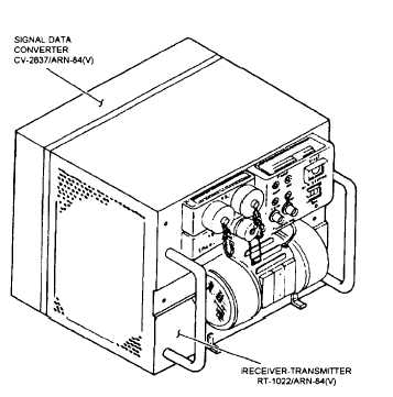
RECEIVER-TRANSMITTER RT-1022/
ARN-84(V).— The RT (fig. 2-14) consists of 10
removable modules mounted on a chassis assembly.
The front panel contains a spare fuse, temperature
gauge, elapse time meter, built-in test (BIT)
indicators, and a BIT switch. The front panel also
contains the antenna connector jack and a blower
motor.
The RT transmits and receives the pulsed RF
signals. It detects, decodes, and demodulates the
signals after reception.
Bearing and slant-range
information is computed in the RT along with
processing of the beacon identification signals. When
the self-test switch is pressed on the control box, the
RT processes the test signals.
SIGNAL DATA CONVERTER CV-2837/
ARN-84(V).— The signal data converter (fig. 2-14) is
mounted to the back of the RT. There is an elapse
time meter on the left side of the converter. This
converter electrically connects the mount and the RT.
Figure 2-13.-TACAN control panel C-9054/ARN-84(V).
Figure 2-14.-TACAN receiver transmitter and signal data
converter.
The signal data converter contains the range and
bearing couplers, an interface, and a buffer. This box
sends the range and bearing data to the indicator
group to be displayed on the indicator. The buffer
regulates the power for the system and acts as an
interface between the RT and the mount. The
interface network enables the range, bearing,
operating mode, channel number, data link, and
digital data to be transferred to the indicator group.
RF TRANSMISSION LINE SWITCH
SA-1818/A.— This switch is an auxiliary unit of the
system. It enables the TACAN set to select the
antenna receiving the strongest signal.
ANTENNA ASSEMBLY AS-2628/A.— The
UHF L-band blade antennae house the antenna
elements used by the TACAN antenna system. These
antennae are used by both the TACAN and the UHF
communication sets.
Operation
Only three of the operating modes will be
discussed here. They are the receive, transmit/
receive, and air-to-air modes. The fourth mode,
beacon, is not used in most aircraft.
RECEIVE MODE.— In the receive mode, the
system will provide bearing and station identity only.
The transmitter is disabled to ensure that radio silence
2-14


